Additional components for GenBoard/VerThree when bought from WebShop
This is a bit old, apparently from the very first v3.0 series. Most stuff is now (v3.3) onboard by standard (on the non-assembled board too). So mostly a review list for the curious, not a todo list.
- GenBoard/Manual/InitialTesting/VerThree - Initial testing and wiring tips (General stuff)
- VEMS/BuildProcedures/SectionThree - Additional components for GenBoard/VerThree when bought from WebShop (Component specific)
Note that at most places there is a huge range of good values (eg. supply caps' capacitance). V3.1 has basically everything installed (except the FETs and IGBTs) that is needed to run an engine fuel, WBO2 and spark, but you probably want to review what does what. And maybe you want knocksensing, EGT
See
- KinderGarden/Components if you are not familier with units (like nF, uF etc...)
- GenBoard/VerThree/RescueKit to find out more about the components in your rescue kits received with the board
Power:
Note that this section is according to one's taste. Some leave out the fuse, transient suppression diode, inductor and does not install extra caps. Others just make a small section from a very thin wire as a fuse. Some people install a lot of supply filtering. Unfortunately the high voltage ramp of the ignition switching (unless you put ignition modules close to the coil on plug transformers) emit some electromagnetic radiation from the wires, no matter how well the supply is filtered.
Recommended setup - this is appropriate in many cases, ask from experts (first put on your MembersPage) if you're not sure
- External 5A Fuse (in the wiring)
- 450mA F1 on PCB for mains
- See GenBoard/BuildProcedures/Stepper (D45 options)
- D37 Transient supression diode. U$5 on the PCB, the biggest diode on the board, right to the main supply regulator, see [picture: big black diode mounted on the bottom on this v3.2]; measure 1k5e22 (or 1k5e18) with your DVM, this is a 22V (or 18V) zener, effectively. If you apply bad power (maybe a sometimes misbehaving alternator), the transient suppression diode usually saves the board (if you apply it! the transient diode is shorted afterwards). Will cost a few traces if you don't apply a fuse, or a fuse if you apply one.
- old buildguides recommend L3=1.5uH, 5.4A in holes of F1 (big standing black headshrinked barrel, with a 1R5 on it: measures appr 0 Ohm with DVM in each direction). It might smooth small voltage fluctuations a bit (negligible anyway), but for rude alternator (or battery break switch that should only be used in case of an accident) that sends huge voltage spikes it actually makes things worse, so not recommended in new installs.
- Just '''get the EC36 pin25 (+12V) to the anode of the small SS24 diode (= cathode of D37, the big throughole 18V transient diode, see above), with a small PTC or fuse (appr 1A without stepper, or 3..4A if stepper is used and heavily loaded), or a wire (a thin wire is OK) instead of the 5.4A inductor.
- C72 10 uF (1210 size, 35V) recommended for best noise reduction. Alternatively 1uF (1206 size, 50V) or as a last chance 1uF (0805 size, 25V).
![[picture: big black diode mounted on the bottom on this v3.2]](http://www.vems.hu/files/genboardv3/images/v3.2/v3.2_0005-lowres.jpg)
Only issue before v3.2:
- U24 for Hall supply (in rescue kit for v3.0, marked "A E"; onboard v3.1)
- D6 on v3.1 you can short the small LM4148 diode feeding the fetdrivers. (it is missing on v3.2 and not really needed at all. We had a report of failure, although it might be related to bad installation with that board).
for serial port' see GenBoard/Manual/CommHardware
Needed for MAP sensor:
- R12 10k
- C10 100nF - 10k and 100nF RC filter (10k * 100nF = 1 msec)
- C11 min: 0,1uF (220nF - 2.2 uF?)
- Cextra10 Optional The [MPX4250A datasheet] suggests a small cap on output of MAP - (pin1=MAP_SIGNAL) to +5V (no individual pads, but easy to put a 0805 SMD cap there) there's a huge range of good values though, use 470pF..1nF if you have (but max 100nF). The datasheet says to GND, but doesn't matter for a cap if it goes to VCC or GND. Except at powerup: it's better if it goes to VCC [AN1646 Noise Considerations]
Needed for Temp sensors:
The best value for these depend on your actual sensors: 2.2 .. 2.7k are usually OK. Some bias can be corrected with easytherm perfectly. It is a very good idea to check operation anyway, so you better calibrate if you are there.
- R9 2,49k for CLT
- R10 2,49k for MAT
Needed for primary and secondary trigger: See
GenBoard/Manual/InputTriggerHardWare
Needed for ExhaustGasTemp: see GenBoard/Manual/ExhaustGasTemp
Needed for acoustic knock sensing:
See GenBoard/Manual/KnockSensor
Needed for IGN:
- Ignition IGBT
- R22, R40, R41, R42, R64 R96, R122, R123 (these gate resistors are preinstalled)
NOT Needed for IGN:
- D11, D18, D19, D20, D26, D30, D33, D34 (leave open)
Injector section
Check out GenBoard/Manual/DDFlyback
Needed for INJ, DR FlyBack suggested:
- FET: FQPF20N06L
- D7, D8, D10, D16, D17, D25, D28, D29 (S2J) You want to connect the flyrail to the positive(+) of injectors (no fuse or switch in between!!)
- R18, R21, R36, R39, R60, R63, R92, R95 (33 Ohm resistors recommended with FETdrivers; max 1k gate resistors without FETdriver, but no PWMing than)
- U3, U6, U8, U9 (when not using FETdrivers, short pin 2 to pin 7 and pin 4 to pin 5 at every place)
Normally using diodes or short here, NOT resistors, check GenBoard/Manual/DDFlyback
- R19, R20, R37, R38, R61, R62, R93, R94 (just short these to 0 ohm)
- Q19, C61, D32, R121 (leave them open)
V3.2, Solder the missing flyback diodes, check GenBoard/Manual/DDFlyback and don't forget the wire from flybackrail to EC36
Needed for 1st channel WBO2:
This part should be dropped, because duplicates GenBoard/Installation/WBOconnect
- R51 510ohm (Pump1+)
- R102 75k (Nernst_Cell1) Do not solder this, if you have only a NarrowBand oxygene sensor!
- R133 10k (Heater 1)
- R134 1k (Heater 1)
- Q18 FET Transistor (Heater 1)
Needed for TPS
The variable resistor type TPS sensor needs GND and +5V input so it can emit an output signal between 0..5V (real range is often just 1..3V, but don't worry, it's configurable). The simpler throttle-idle-switch only requires GND, but that is not a real TPS anyway.
- populate R142 (270 ohm) and C69 (220 nF) which makes a current-limited supply for your TPS. These (R142 and C69) are not automatically populated on V32 either, since some people uses this EC36 pin for other purposes (eg. input pin) and applies an "offboard R142" in the wiring for the TPS.
- Refrain from using the HALL5V signal directly unless absolutely needed (eg. for HALL sensor supply). Especially avoid shorting it to GND (the onboard 78L05 limits to 100mA and it might survive for some time, but it's not guaranteed).
Needed for bipolar stepper motor control
- Stepper chip (DIP16) L293NE or SN754410
- if you want inductive load on stepper lines (not unlikely, eg. stepper motor is inductive) you want to short the diode D45 (which powers the stepper chip) with 2.5 .. 5A fuse (or with some experience a thin wire ~ poor man's fuse) parallel with a reverse populated D45 (yes! anode on the stepper chip side).
- 8 x S2.. stepper flyback diodes on the bottom. Only required for L293NE (that is not sold in WebShop for a long time now), not necessary for the common SN754410 as SN754410 has internal clamping. For L293NE make absolutely sure the 8 pieces of S2.. diodes at the bottom side of the stepper driver are soldered in (only possible on v3.0 or v3.1, pads removed from v3.2). If you drive resistive load, these flyback diodes are not needed, since the resistive load will not activate the FlyBack (but the inductive will).
Not Needed:
- R5 PEN on AtMega
- C49 Fuel Pressure
- even the reset circuit (wether RC or MCP809 type) can be dropped (the AVR has internal brown-out protection, and pullup on reset line)
Recommended checklist for v3.3
Applies for genboard v3.3 sent out before 2006.jan.20. For nonassembled, recommended to check regardless the time of sending out.
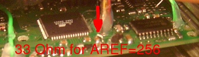
This changes to AREF=256 (from AREF=287):
Same, but in another perspective:
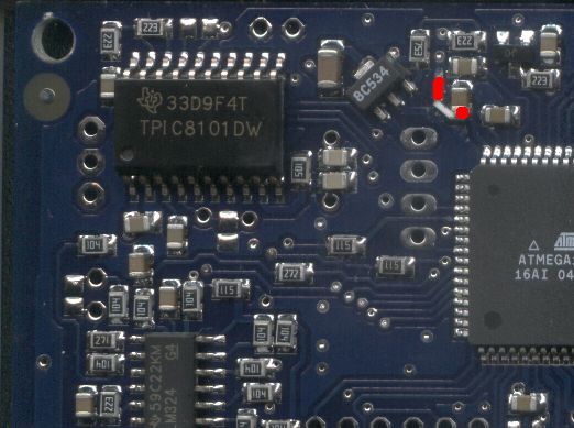
And on v3.2, there are pads for the component, but solder a 0 Ohm resistor or small thin wire (eg. one hair from a stranded wire). Some tests indicate that 0 Ohm or small wire is better than 33 Ohm if the GND5 sees high current and voltage fluctuations (usually because of directly driven ignition coils).

I only removed endplate on mine. The capacitor endcap is easy to solder to. Scratch the solderprotect from the end 6..7 mm of the longer 5V trace to solder to.
The modification effects:
- temp tables. AREF=256 is more standard (and allows measurement of lower min temp, down to -40C), see EasyTherm
- wbo2_nernstdc_target=0x89 (decreases from 0x9c or so)
- kpafac=7F (instead of 78 or so: for 250kPa MAP sensor)
- cleaner MAP measurement (either onboard of offboard MAP)
- batt_cal increases appr 10% typically from 0xA9 (decimal 169) to 0xBB (decimal 187). Actually, this is the easy way to tell AREF without opening the box:
- calibrate batt_cal, it's easy: measure supply voltage with DVM and look at battery voltage in megatune or LCD (page6: mlp06). Adjust (in MegaTune or manual command in TerminalProgram or keyboard) for best match. If it's near 187 or 188, the AREF=256 is applied, great !
This small resistor powers AVCC-AVR. Without this, it is powered by a diode inside the AVR (it was an unintentional change in v3.3) giving a voltage drop (that can be compensated with configuration).
Note that AREF is powered from inside the AVR (using a setting in firmware) from the AVCC-AVR (and just needs decoupling cap on the external pin). This is OK this way. This seems to have confused hw-designers somewhat about the AVCC.
- if using secondary trigger HALL (or both HALL and VR, referred as auditrigger) see GenBoard/Manual/InputTriggerHardWare/ReplaceC
- if using powerflyback, see GenBoard/Manual/PowerFlyback/RemoveD
See also