The trigger hardware is configured according to order options (or order comment), and should not usually need any tamper inside the ECU
- primtrig is simpler (also, primtrig circuit was not extended between versions)
- at worse (rarely) some external pullup resistor (eg. 33k..47k) needed if the harness/setup is noisy, but VR signal is strong enough even in winter slow-cranking.
- sectrig was extended with onboard provision for AudiTrigger/CamHALLInverter
- the circuit is simple after identifying actual version and setup
- sectrig=HALL example: GenBoard/Manual/InputTriggerHardWareSectrigHall
It is best to order with desired options (assembled controller, or with bare v3 use order comments). If you need to modify trigger hardware, also see GenBoard/VerThree/Schematic
The trigger signals are sensitive. Especially the VR signal with low pulsecount and/or at low-RPM (cranking). VR is not really sensitive from noise via capacitive coupling (although long wires that drive ignition coils arranged parallel might inject noise) but rather to noise injected through ground loop (switched power-currents that partially sneak through GND instead of GND5) if not installed properly.
- If GND5 is not connected, you get smoke from the ECM.
- If only 1..2 GND5 wire connected instead of 4..5 you get more ground-noise.
- If GND-GND5 bridge (a soldered "arch" left to the 4 FETdrivers, 30mm under VEMS logo on top side) is still soldered (and not cut), you get the ground-loop that injects noise into VR and might make startup problematic
The following precautions highly recommended:
- use shielded cable. The cable must have at least 2 wires besides the shield: the GND and the signal itself (VR- and VR+)
- The shielding must be connected on the ECU side only, so the shielding is NOT actually used for connecting the GND signal to both ends
- use GND (for VR-) and not GND5. The GND5 signal would make the signal noisy (when FETs and IGBTs switch).
- connect sensor GND only near the EC36 connector (not at battery and not at other places). Search the web for "ground loop" if you want to understand in more depth.
- External resistor for stronger VR pullup helps eliminate VR signal noise (eg. grounds and shielded cable already properly connected; it's all OK without sparks, but noise interference experienced from spark or wbo2 ):
- external 27k..47k between VR input (eg. EC36/27 for primary trigger) and +5V (EC36/29 can be used if nothing else connected there; otherwise EC36/28 or other stable +5V supply)
- historical note: R30 (primtrig VR input pullup resistor inside ECU) appr. 18k; (was 27k 2012~2014 useful for unusually low-VR-amplitude installs; pullup can always be made stronger by external pullup).
- Measure input pullup resistor value without opening the box: connect 1k resistor INSTEAD of VR sensor (between GND and trigger or analog input): pullup_kOhm = 5 / measuredVolt -1
- for example 5 / 0.178 -1 = 27 k when you measure 0.178V (+178mV DC bias). It is good practice to always document this voltage (and required in case of any trigger issues), and document the measured VR sensor resistance.
Motronic55 / Audi AAN / [v3.9AAN mainboard] (primary trigger=VR; secondary trigger=auditrigger; or nonstandard/custom: HALL/HALL)
v3.6 (or newer)
Some nice pics on MembersPage/Larsa/VEMSpictures
Primary trigger is same as v3.3 - see v3.3 primary trigger=...
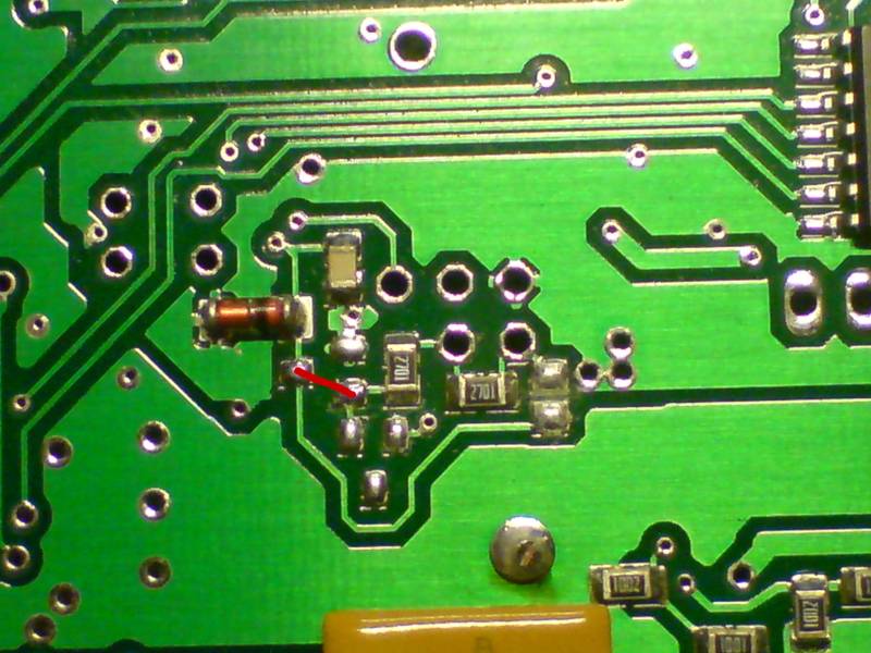
- for secondary trigger HALL (or sectrig unused), a small blob ("electric-short") is needed between the SOT23 NPN base to collector (transistor not populated, just a small short to route the signal) as shown with red on the image
- Concentrate on the 5 (2+3) throughole pad in the middle, and its surroundings: the resistors must look as on the image (label 2701 or 272 is 2k7 resistor)
- all 5 throughole pads in the middle must be empty: if it was originally sectrig=VR, REMOVE THE WIRE going to the board (going to the 10k before LM1815/pin3)
- double-check the resistors on the board to be placed on same positions as on image
- the left-side 2701 can be higher than 2k7, max 10k is also allowed there
- Verify this: that HALL-input pullup towards +5V is appr 2k7..4k7 (the right-side 2701 on the image). The signal should be min 3.3V when input is open.
- Should measure 3.7V or higher (absolute min 3.3V) at EC36/13 (or the CPU side of SJ7) when powered up and input not connected
- If you pull down the signal with a 1kOhm resistance, than measured DC voltage should be minimum 870 mV (voltage divider equation: U=5V * R/(R + Rpullup))
- if you had sectrig=VR or sectrig=auditrigger (and converting to secrig=HALL), than also
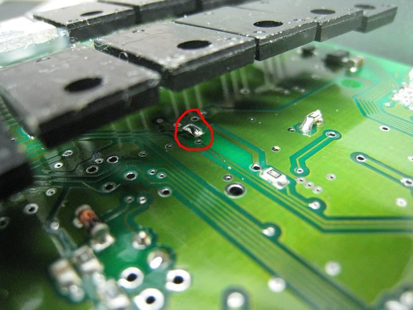
- open SJ7 solder-blob on the bottom, so LM1815pin12 output is DISconnected from the microcontroller input pin. This blob is on the bottom, close, to the line of FETs.
- actually this is the only step required if converting from sectrig=auditrigger (because that already has the HALL part of the circuit set up from EC36/13)
Secondary trigger setup is also similar to v3.3 but more versatile, allowing
- for secondary trigger=auditrigger (combined setup of crankhome VR and camHALL masking, possibly with onboard cam-HALL inverter)
- there is onboard provision for AudiTrigger/CamHALLInverter. A SOT23 NPN (like BC817 but almost any NPN transistor would work) in place of the red mark on the pic above, and a 2k7 pullup resistor (a bit to the right)
- The second LM1815 and the related blob at the PCB bottom under the FETs is needed. (same as with v3.3 sectrig VR setup)
- for secondary trigger=VR (when not using the 3-sensor auditrigger), we recommend that EC36/13 is used as sectrig VR input. This way EC18/12 can be used for analog input (0-5V, sensitive mcp3208 input).
- The second LM1815 and the related blob at the bottom side under the FETs is needed.
- wether you order assembled or assemble yourself, read the recommended econoseal pins at [webshop page]
Primary trigger
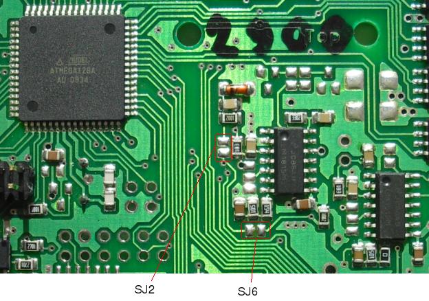
The image shows the config solder blobs.
- for primary trigger VR
- SJ2 open, SJ6 closed
- R30 pullup - install (approximately) 18k resistor (27k also works, but 18k is usually more generic). It is marked 2702 or 273 for 27k, 1802 or 183 for 18k.
- for primary trigger HALL
- SJ2 closed, SJ6 open
- R30 pullup - install 4k7 resistor, it is marked 4701 or 472.
v3.1 (trigg1) primary trigger=HALL
For Hall setup:
- R30=2k7 (pullup resistor. 10k is a bit too high)
- C88 = does not matter
- short SJ1
- R55=10k
- do NOT short SJ2
- remove R56(=10k, next to SJ2)
- and solder SJ2=150k (or at min 47k resistor; this makes RC filter with the IC1 line's appr. 10..20pF - which comes from AVR input capacitance + trace capacitance)
- do NOT short SJ6
- The other parts near the LM1815 do not matter
v3.1 (trigg1) primary trigger=VR
- R30 pullup resistor NOT soldered (unsolder it if there). A few mm left from the 2x3 trigger pinheader. R30 is the horizontal, 0805 package; further away from the EC36
- C88 = does not matter
- R55=10K
- short SJ1
- do NOT short SJ2
- short SJ6
- D14 is optional (3.9..5.1V zener diode)
- U11 (LM8515)
- R56 (10K) resistor of input RC lowpass
- C30 capacitor of input RC lowpass (1..3.3nF for multitooth, upto 100nF for coiltype-only-for-sure setup)
- R57 (75K)
- R87 (1 .. 1.6M) resistor of peak-detector
- C38 (0.22uF) capacitor of peak-detector
- R88 (10K) output pullup resistor
- C31 (1nF)
- C39 (0.22uF)
- measure with DVM 200kOhm range between primary trigger (trigger1_conn) signal and LM1815 pin3. If >21kOhm than you don't have VR input selected. Check around SJ1
- follow the path on the GenBoard/VerThree/Schematic, from the inputtrigger to the LM1815 input pin: Identify the components that are in the path
- measure with DVM 2kOhm range between LM1815 pin12 to AVR's pin29 (IC1). If > 10 Ohm, than SJ6 is not shorted
- apply self stim, it only requires a 1..10uF capacitor and a few simple menu-commands (see OutputTrigger) and it can save you hours. Don't skip this unless the trigger setup works immediately.
v3.2 / v3.3 (trig1) primary trigger=VR - most parts are soldered. Still check at least the SJ6 and R30.
THIS IS THE MOST COMMON SETUP - therefore it is described with picture on the trigger main page: GenBoard/Manual/InputTrigger
- on v3.2, check that R30 pullup resistor NOT soldered (unsolder it if there). A few mm left from the 2x3 trigger pinheader. R30 is the horizontal, 0805 package; further away from the EC36. On v3.3 this is not soldered in factory
- short SJ6 (right below LM1815) by soldering a very short wire
- connect primary trigger input to the internal signal directly (no capacitor needed, just a very short wire). Either
- put a jumper: connect the upper-middle pin to the upper-right pin of 3x2 pinheader (viewing from the "Top" side)
- or rather solder on bottom of the board to short JP2 and JP7 : connect upper-middle to upper-left pin (viewing from the "Bottom" side)
The 3x2 pinheader is between the EC36 and the LM1815, but
- on v3.2 it has an additional GND pad besides the 3x2 pins.
- on v3.3 it lacks a pin (so only 5 pin instead of 6) because trig2 is connected with PCB trace
Make sure you view the board in a good orientation, so econoseal points down and "Top" or "Bottom" text is readable.
v3.2 (trig1) primary trigger=HALL
- solder JP2 & JP7: this is the top right of the 2x3 header; red on the [image]
- short SJ2
- do NOT short SJ6 (remove the blob if there)
- R30=2k7 pullup resistor (2k .. 4.7k). Note that 10k is a bit too high
- remove R56(=10k, next to SJ2). This is not strictly necessary if R30 is 4k7 or lower.
- measure DC voltage between SJ2 and GND (with board powered, but HALL sensor not connected or inactive): must be higher than 3V
![[image]](http://www.vems.hu/files/genboardv3/images/v3.2/v3.2_top_trigg_jumpers.jpg)
v3.3 (trig1) primary trigger=HALL
- solder JP2 & JP7: this is the top right of the 2x3 header; red on the [image]. The same area of v3.3 looks slightly different (no bottom-right pad, where the blue jumper sits on the image), but never mind. The primary trigger is the same, the changes are at the secondary trigger, eg. 1 throughole pin dropped, and R48 moved to bottom.
- short SJ2
- do NOT short SJ6 (remove the blob if there)
- R30=2k7 pullup resistor (2k .. 4.7k). Note that 10k is a bit too high
- remove R56(=18k, next to SJ2). This is not necessary if R30 is 4k7 or lower.
- measure DC voltage between SJ2 and GND (with board powered, but HALL sensor not connected or inactive): must be higher than 3V
[ Converting from VR to HALL (Swedish)]
v3.2 (trig2) secondary trigger=HALL
[Picture of 2x3 header, SJ6, SJ2 on Genboard v3.2] R56 and C30 are right after SJ2 (LM1815 pin3).
- connect JP5 & JP13 (jumper bottom right of the 2x3) as on the above pic
- R91=10k
- short SJ10 (or short C89)
SJ5
There are 2 schools, one says to short SJ5 (this should work well, with no difference for a good signal). The other likes a bit extra filtering and says:
NOT short SJ5
- recommended SJ5=150k (resistor; this makes RC filter with the IC3 line's appr. 10..20pF - which comes from AVR input capacitance + trace capacitance)
v3.2 Primary and Secondary setup for Hall - similar instructions as above
- Bottom view [Picture of trigger area]
- Top view 1 [Picture near jumpers]
![[Picture of trigger area]](http://www.vems.hu/files/MembersPage/MattiasSandgren/Trigger/hall_v3.2_bottom_view.jpg)
![[Picture near jumpers]](http://www.vems.hu/files/MembersPage/MattiasSandgren/Trigger/hall_v3.2_top_view_1of2.jpg)
Notes - apply both for primary an secondary trigger
- The jumpers are in place for the trigger signals, should be soldered on the bottom of the board for better vibration resistance.
- added 1n capacitors between ground and each trigger signal. Actually on the pads of D14 and D17 (originally ment for 5V1 zener diodes), but other places can be OK as well.
Primary trigger related:
- Top view 2 [Picture near LM1815 chip]
- R30=1k strong pullup resistor
- shorted SJ2
- removed R56 (103=10k), the resistor next to SJ2
![[Picture near LM1815 chip]](http://www.vems.hu/files/MembersPage/MattiasSandgren/Trigger/hall_v3.2_top_view_2of2.jpg)
Secondary trigger related:
- R48=1k strong pullup resistor
- shorted SJ5 (on the bottom)
v3.0 .. v3.1 secondary trigger (Trigg2) VR setup (with LM1815)
U12, R58, R59, R89, R90, R91, C32, C33, C34, C40, D24, D27, SJ7 & SJ10 (shorted)
v3.2 secondary trigger (Trigg2) VR setup (with LM1815)
Solder
- LM1815
- SJ7
v3.3 secondary trigger=VR hardware setup (traditionally the AudiTrigger setup was used for this, with masking cam-HALL unconnected)
- while SJ7 is open, with cam-HALL masking signal unconnected you can measure that R48 (2k7 recommended) pulls up D27 cathode to 3.5V or higher. This is a good verification !
- after SJ7 is shorted, unfortunately this cannot be measured (except with scope with input pulses applied)
- SJ7 solder-blob on the bottom, so LM1815pin12 output is connected to the microcontroller input pin. This blob is on the bottom, under the FETs.
- solder the 2nd LM1815 (same orientation as first: pin1 closest to atmega)
- wire from EC18pin12 to the 2nd LM1815 input pad (that goes through a 18k resistor to pin3 of the second LM1815)
- 1k pulldown resistor between VR input signal and GND
- this is effectively in parallel with the VR sensor. Scratch the green solderprotect a bit at the GND so an SMD resistor can be soldered
- To make it work with the 1k VR-input pulldown resistor, connect LM1815 pin5 to +5V with the SJ4 (3pin jumper): solder the mid-pin to the +5V pin that goes LM1815pin8
- R182=0 resistor (or short) at LM1815pin7. This helps the adaptive hysteresis (quicker charge). Has the same function as R181 >= 100k for the first LM1815 (soldered in factory) but 0 Ohm (short) is more appropriate here.
- optionally increasing the neighboring 220nF capacitor by adding an additional (solder piggyback) +1uF or +2.2uF might be a good idea
Also,
- for auditrigger, remove C103 or replace with 1nF
- only necessary if the secondary_trigger HALL signal is actually used
- so C103 is don't care when only the VR is used because than the "masking HALL" is an internal constant signal.
- But it won't hurt to do it in any case, this is the standard. Assembled controllers sent out after 2005.12.31 have C103 replaced. If you assembled yourself, or actually use HALL secondary trigger with an assembled controller sent out in 2005, see GenBoard/Manual/InputTriggerHardWare/ReplaceC103
- don't forget to set up primary trigger (usually for VR, see above)
- Check [assembled controller item] for current standard options
Warning:
EC36pin13 is set up for "masking HALL" (nothing to do), but beware, that this setup (with the SJ7 blob shorted) does NOT work for HALL only secondary_trigger ! :
- OK: EC18pin12=VR, EC36pin13=masking cam HALL (for audi's 3-signal system)
- OK: EC18pin12=VR (EC36pin13 not connected) not for audi, but for a 1-tooth VR-type cam signal (like in Fiat Stilo)
v3.3 Secondary trigger (Trigg2) Hall setup:
- remove C103 or replace with 1nF
- only necessary if the secondary trigger HALL signal is actually used, but for new installs, best to do it in any case, so this is the standard. Assembled controllers sent out after 2005.12.31 have C103 replaced. If you assembled yourself, or actually use HALL secondary trigger with an assembled controller sent out in 2005, see GenBoard/Manual/InputTriggerHardWare/ReplaceC103
Special setup: VR, when input does not go below 0V - very rare!!!
You only need a series capacitance (eg. 10uF, 1210 package, 25V or 35V) when the signal otherwise does not go below 0 Volt. The capacitor allows a voltage difference, but still forward the signal.
Useful, for example when stealing the 0.65V based VR signal of an alien ECM (as on MembersPage/Gabor). SJ1 must not be shorted in this case.
- for v3.0 and v3.1: C88=10uF
- v3.2 and v3.3: 10uF, 25V (or bigger) cap must be soldered instead of the input jumper (that is between JP2 and JP7)
The rest of the VR setup is as usual, see in the relevant section (make sure R30 pullup resistor is not soldered!)
See also
- GenBoard/Manual
- GenBoard/VerThree/Schematic
- GenBoard/Manual/InputTriggerHardWare/AudiTriggerHardware and InputTrigger/AudiTrigger
- [introduction] to VR and HALL sensors
- GenBoard/VrInputWithHallSensor - weird setup