2nd COM wiring
2nd COM port for live data (FW 1.2.35 and newer), 2nd RS232 3 pin (unpopulated header) towards the main processor:
- GND (easy to locate)
- TX (measures appr -7V when idle)
- RX (input, as an experiment pull to +5V with 1k resistor and it will follow to 3..4V perhaps).
Located above the MAX232D (SOIC16) chip, different header, otherwise the same pinout as the 1st RS232 (which is towards the L293D stepper driver IC). See GenBoard/VerThree/Schematic
Ref. link for AIM stream: BroadcastDatastreamAim
Able to use external wideband controller for logging and EGO?
Curious if it is possible to use an external WB controller output (0-5v) connected to analog input on VEMS and have VEMS use it for EGO correction feedback, etc?
For logging: of course (any analog input can be logged)
- for EGO, the internal controller is better than an external, because it has access to "confidence" data also (eg. if nernst or heater-ri target is reached or not, and so on...), not practical via a 0-5V link
- would be possible with serial (RS232, RS485, CAN, ...) link but this is currently only one-directional: v3 => other devices
- almost practical with a frequency or PWM signal
- note: it is possible to get an external controller influence lambdatarget or fuel pw via a 0-5V v3 analog input: via anytrim function
Honda NSX trigger use
Honda NSX has a 24 tooth crank teeth (mounted on cam, one on each bank) + 1 tooth cam sync tooth (also inside same pickup).
So 24+1, both cam and crank are VR sensors. Is this a possible trigger arrangement that the VEMS would be capable of?
24+1 is supported (actually a basic type). Checkout "configlet" ( VemsTune / "Primary Trigger" dialog, bottom entry).
For any VR, make sure to apply good polarity: GenBoard/Manual/VrSensor/Polarity
- 24+1 is not listed in the configlet, 24-1 is (missing tooth), but this is not a missing tooth setup. Crank wheel is located on the cam and is 24 tooth (no missing) plus an extra cam sensor with 1 tooth.
Can I assume that using the 4 cyl 12+extra option (coil type) would be correct for this application? Choose that (the "trigger visual" dialog might be helpful for this also), and verify primtrig settings:
- coil type
- nr of teeth (per engine cycle)=24
- tooth width = 30 crankdeg
- reference teeth: 0, 6, 12, 18 (order of arrow)
- check "Validate" (if it warns of something of importance)

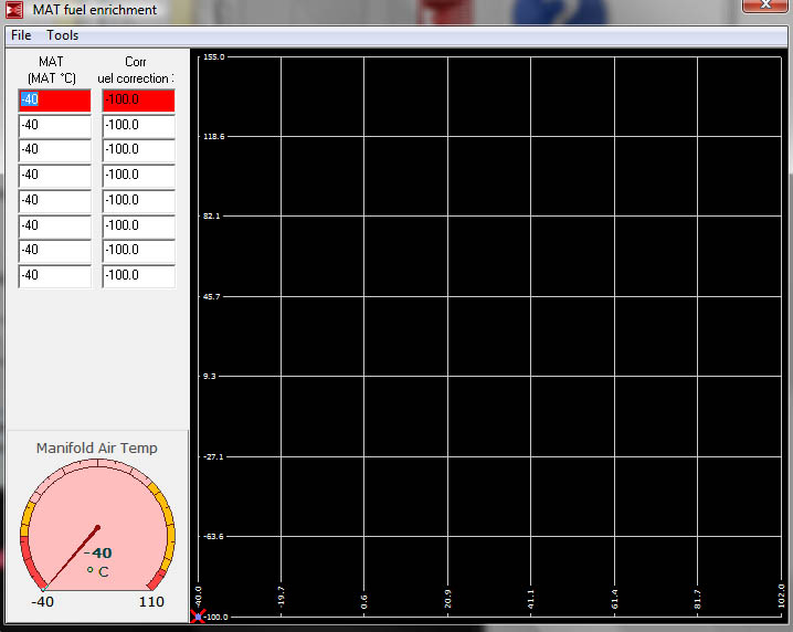
New MAT Enrichment table base configuration
I have noticed that the new firmwares are being compiled with an 8x8 table to configure fuel correction based on MAT. Problem is, I cannot find an explanation as to what the scaling is.
- As usual with enrichments, 100 is 100%
- See the "View / Group / Calc model" where the effect of fuel pw modifiers can be seen in action (with intermediate results).
- If in doubt, rather easy to apply eg. 50,100 and 200 to a cell, and see effect.
Also some defined default values should be given, which can then later be trimmed according to application.
Defaults are given in every ECU sent
- if that is lost, in VT install dir, find sg like: defaultfirmwareconfigs/config_1.2.11.vemscfg
This is the screen I am referring to (1.0.79rc2 firmware):
What defaults should we be using.
Bosch IAC:
I quick drawing I made of the flyback for use with the 2 PIN Bosch PWM IAC (spring type). Thanks again to Jorgen for helping me with this!

Here are 2 good printable degree wheels that might help someone get their project going when it comes time to setup their crank trigger.

![[Degree Wheel 1]](http://savetheledges.org/test/AVS/images/tech/CrankDegreeWheel.png)

![[Degree Wheel 2]](http://www.vespamaintenance.com/elec/timing/degwheel.jpg)
Here a factory VW press on crankshaft 60-2 wheel and sensor:
Part numbers:
For wheel and seal rings/mounting plastic - 030 103 171 L
For sensor - 030 906 433 Q

![[Wheel and sensor]](http://img339.imageshack.us/img339/2812/drehzalgebertv8.jpg)
- TerminalProgram
- disconnect megatune
- term @ 9600,8n1 connect (COM1 or whatever)
- Man
- mll - sends LCD content, just to test if we are in "Man" menu
- start log
- mcd - so log contains config
- mct - so log contains tables
- mdd0c
- cranking (4..5 sec)
- stop log
- upload log to internet
- bye (this changes mode to MegaTune binary protocol; a reboot does the same)
http://www.vems.hu/wiki/index.php?page=GraphicalDisplay
Information was taken from GrmRacers WIKI page, thanks to him everyone that uses 60-2 setups has an easy way to get the information they'd need. So I copied it here for my own reference. But all credit goes to him! :)
MegaTune is an easy way to setup the trigger values, but you need to know what you are changing.
current decimal values
| Primary Trigger | GRM setup | Mcel | ||
| Edge | Rising | Rising | ||
| Type | Multitooth | Multitooth | ||
| Filtering | Disabled | Disabled | ||
| Tooth Relation (Usually Disabled) | Disabled | Disabled | ||
| Trigger Settings | ||||
| TDC after trigger (degrees) | 60.0 | 60.0 | VAG wheel on ABA block is 90d off TDC at the center of the missing teeth via calibrated eyeball | |
| Number of teeth on wheel | 58 | 58 | actual nubs | |
| Trigger Tooth | 3 | 15 | The third nub after the space actually the missing ones are counted, 3= the first after the space | VAG ABA wheel appears to have the center of the missing teeth @ 90d off TDC, would this make this value 2 |
| Next Trigger Tooth | 15 (V8)/20 4clyn | 15 | Manual states NextTrigTooth= imaginary teeth * 2 / cylinders (60 *2 / 4 = 30) | |
| Crank minimum period (usec) | 1280 | 1280 | ||
| Tooth Width | ||||
| Engine Phase, when reset | 240 | 240 | determines toothwidth unit; (equivalent to 720 crankdegrees = 2 crankrot= 120 teeth) | |
| Angular width of tooth | 2 | 2 | 120 teeth is 240, so 1 tooth width is 2 | |
| Angular width of missing tooth | 6 | 6 | 3 times the above (2 missing teeth) |
| This part needs to be made either transparent to the end user or extremely well explained with a shortcut on howto do it. | ||
| Tooth Relation to Normal (usually 181) | 181 | 181 |
| Tooth Relation to Missing (usually 118) | 118 | 118 |
These are all you settings, but these are not normally how motorheads describe thier motors or triggers.
Typical Descriptions
- TDC -- Regular meaning when #1 cylinder is at top of rotation
- Number of actual teeth on wheel
- Number of missing teeth on blank spot on wheel if there were teeth there
- Relation of blank spot to TDC this would be in degrees
- Leading edge angle from TDC
- Trailing edge angle from TDC
So using these values how do we get the other ones.
Suggestion
Do the number trunkation etc in the make mtt portion. Most NON - EE/CompEE/CS engineers will not get the howto about converting decimals to an arbitrary (seemingly) number less than 255 ( 8-bit micro unsigned issue)...
So basically a good picture and straightforward equation, IF it is not automagically done for the config. If they don't care, they should copy a working example and not mess with the numbers they don't know.
Min Crank Period (review this statement)
This definately needs to be calculated somewhere else.. I thought it was for "cranking" aka starting the car. but it is directly related to Rev limiter.. you could call this the OVERREV point or something. I'm guessing its an early variable.
Angular width, etc.. This should all be auto-calculated.
since an 8bit number only can goto 255 (8-bit unsigned) so the whole point of this is scaling.
Example 60-2 wheel
- 1 its a ratio..
- 720d / 255 = 120teeth/ x ; x = 8bit approximation of degrees / tooth but this has to be rounded down so that it is a nice root ie. divisible and integer like.
- 2 Given the number of teeth in a 720d rotation what is the new number in this ratio
- 120teeth/ rounddown(x)= 720d / y
- y is the new normalied max value (y <= real angle per tooth )
- (y)(number of teeth) = engine Phase
- Engine phase refers to the new number y * number of teeth that represents 720d
- The proper name would be scaled 720d value
- 3 Scaled Tooth angle is y
- 4 Scaled missing tooth angle is y * # of missing teeth
Proposed table
| Typical Meaning | Variable names | 1-10 | 1-12 | 1-16 | 1-36 | 60-2 | ||
| Total Teeth | Entered | internal | 10 | 12 | 16 | 36 | 60 | |
| missing teeth | Entered | Number of teeth missing | 1 | 1 | 1 | 1 | 2 | |
| Teeth Present | Calc | Number of teeth on wheel | 9 | 11 | 15 | 35 | 58 | |
| Crank Rotations per complete clycle | Entered | internal | 2 | 2 | 2 | 2 | 2 | (2 for 4cycle 1 for 2 cycle) |
| Degrees per complete cycle* | Calc | internal | 720 | 720 | 720 | 720 | 720 | |
| 720 / Total Teeth = Angle Per tooth (degrees) | Calc | 36.0 | 30.0 | 22.5 | 10.0 | 6.0 | ||
| Total Degrees scaled to 8 bit unsigned: 255/total teeth | Calc | 12.8 | 10.6 | 8.0 | 3.5 | 2.1 | ||
| Truncate for integer math | Calc | 12 | 10 | 7 | 3 | 2 | ||
| Scaled degrees per cycle | Calc | EnginePhase when reset | 240 | 240 | 224 | 216 | 240 | |
| Scaled degrees per tooth | Calc | Angular width of tooth | 12 | 10 | 7 | 3 | 2 | |
| Scaled degree of missing spaces(teeth+1) | Calc | Angular width of missing tooth | 24 | 20 | 14 | 6 | 6 | |
Now you have to Determine what the next trigger tooth is
| Number of Clynders | |||||||
| 4clyn | Entered | 4 | Good | Good | Good | Good | Good |
| Teeth until next clyn event | Calc | Next trigger tooth | 5.00 | 6.00 | 8.00 | 18.00 | 30.00 |
| Calc | Scaled deg/ cylinders | 60.00 | 60.00 | 56.00 | 54.00 | 60.00 | |
| 5clyn | Entered | 5 | Good | NotValid | NotValid | NotValid | Good |
| Teeth until next clyn event | Calc | Next trigger tooth | 4.00 | 4.80 | 6.40 | 14.40 | 24.00 |
| Calc | Scaled deg/ cylinders | 48.00 | 48.00 | 44.80 | 43.20 | 48.00 | |
| 6clyn | Entered | 6 | NotValid | Good | NotValid | Good | Good |
| Teeth until next clyn event | Calc | Next trigger tooth | 3.33 | 4.00 | 5.33 | 12.00 | 20.00 |
| Calc | Scaled deg/ cylinders | 40.00 | 40.00 | 37.33 | 36.00 | 40.00 | |
| 8clyn | Entered | 8 | NotValid | Good | Good | Good | Good |
| Teeth until next clyn event | Calc | Next trigger tooth | 2.50 | 3.00 | 4.00 | 9.00 | 15.00 |
| Calc | Scaled deg/ cylinders | 30.00 | 30.00 | 28.00 | 27.00 | 30.00 | |
| 10clyn | Entered | 10 | Good | NotValid | NotValid | NotValid | Good |
| Teeth until next clyn event | Calc | Next trigger tooth | 2.00 | 2.40 | 3.20 | 7.20 | 12.00 |
| Calc | Scaled deg/ cylinders | 24.00 | 24.00 | 22.40 | 21.60 | 24.00 | |
| 12clyn | Entered | 12 | NotValid | Good | NotValid | Good | Good |
| Teeth until next clyn event | Calc | Next trigger tooth | 1.67 | 2.00 | 2.67 | 6.00 | 10.00 |
| Calc | Scaled deg/ cylinders | 20.00 | 20.00 | 18.67 | 18.00 | 20.00 |
The min_crank_per describes the minumum time between 'valid trigger events. If you use this table select your # of clynders and RPM limit. and then just plug in that number
____
| minmum period in microseconds(us) between trigger events | |
| Assumes Crank Trigger | # of clynders |
| RPM limit | Safety Margin | 2 or 4 cycle | 4 | 5 | 6 | 8 | 10 | 12 |
| 1000 | 1000 | 4 | 15000 | 12000 | 10000 | 7500 | 6000 | 5000 |
| 1500 | 1000 | 4 | 12000 | 9600 | 8000 | 6000 | 4800 | 4000 |
| 2000 | 1000 | 4 | 10000 | 8000 | 6667 | 5000 | 4000 | 3333 |
| 2500 | 1000 | 4 | 8571 | 6857 | 5714 | 4286 | 3429 | 2857 |
| 3000 | 1000 | 4 | 7500 | 6000 | 5000 | 3750 | 3000 | 2500 |
| 3500 | 1000 | 4 | 6667 | 5333 | 4444 | 3333 | 2667 | 2222 |
| 4000 | 1000 | 4 | 6000 | 4800 | 4000 | 3000 | 2400 | 2000 |
| 4500 | 1000 | 4 | 5455 | 4364 | 3636 | 2727 | 2182 | 1818 |
| 5000 | 1000 | 4 | 5000 | 4000 | 3333 | 2500 | 2000 | 1667 |
| 5500 | 1000 | 4 | 4615 | 3692 | 3077 | 2308 | 1846 | 1538 |
| 6000 | 1000 | 4 | 4286 | 3429 | 2857 | 2143 | 1714 | 1429 |
| 6500 | 1000 | 4 | 4000 | 3200 | 2667 | 2000 | 1600 | 1333 |
| 7000 | 1000 | 4 | 3750 | 3000 | 2500 | 1875 | 1500 | 1250 |
| 7500 | 1000 | 4 | 3529 | 2824 | 2353 | 1765 | 1412 | 1176 |
| 8000 | 1000 | 4 | 3333 | 2667 | 2222 | 1667 | 1333 | 1111 |
| 8500 | 1000 | 4 | 3158 | 2526 | 2105 | 1579 | 1263 | 1053 |
| 9000 | 1000 | 4 | 3000 | 2400 | 2000 | 1500 | 1200 | 1000 |
| 9500 | 1000 | 4 | 2857 | 2286 | 1905 | 1429 | 1143 | 952 |
| 10000 | 1000 | 4 | 2727 | 2182 | 1818 | 1364 | 1091 | 909 |
| 10500 | 1000 | 4 | 2609 | 2087 | 1739 | 1304 | 1043 | 870 |
| 11000 | 1000 | 4 | 2500 | 2000 | 1667 | 1250 | 1000 | 833 |
| 11500 | 1000 | 4 | 2400 | 1920 | 1600 | 1200 | 960 | 800 |
| 12000 | 1000 | 4 | 2308 | 1846 | 1538 | 1154 | 923 | 769 |
| 12500 | 1000 | 4 | 2222 | 1778 | 1481 | 1111 | 889 | 741 |
| 13000 | 1000 | 4 | 2143 | 1714 | 1429 | 1071 | 857 | 714 |
| 13500 | 1000 | 4 | 2069 | 1655 | 1379 | 1034 | 828 | 690 |
| 14000 | 1000 | 4 | 2000 | 1600 | 1333 | 1000 | 800 | 667 |
| 14500 | 1000 | 4 | 1935 | 1548 | 1290 | 968 | 774 | 645 |
| 15000 | 1000 | 4 | 1875 | 1500 | 1250 | 938 | 750 | 625 |
| 15500 | 1000 | 4 | 1818 | 1455 | 1212 | 909 | 727 | 606 |
| 16000 | 1000 | 4 | 1765 | 1412 | 1176 | 882 | 706 | 588 |
| 16500 | 1000 | 4 | 1714 | 1371 | 1143 | 857 | 686 | 571 |
| 17000 | 1000 | 4 | 1667 | 1333 | 1111 | 833 | 667 | 556 |
| 17500 | 1000 | 4 | 1622 | 1297 | 1081 | 811 | 649 | 541 |
| 18000 | 1000 | 4 | 1579 | 1263 | 1053 | 789 | 632 | 526 |
| 18500 | 1000 | 4 | 1538 | 1231 | 1026 | 769 | 615 | 513 |
| 19000 | 1000 | 4 | 1500 | 1200 | 1000 | 750 | 600 | 500 |
| 19500 | 1000 | 4 | 1463 | 1171 | 976 | 732 | 585 | 488 |
| 20000 | 1000 | 4 | 1429 | 1143 | 952 | 714 | 571 | 476 |
| 20500 | 1000 | 4 | 1395 | 1116 | 930 | 698 | 558 | 465 |
| 21000 | 1000 | 4 | 1364 | 1091 | 909 | 682 | 545 | 455 |
| 21500 | 1000 | 4 | 1333 | 1067 | 889 | 667 | 533 | 444 |
| 22000 | 1000 | 4 | 1304 | 1043 | 870 | 652 | 522 | 435 |
| 22500 | 1000 | 4 | 1277 | 1021 | 851 | 638 | 511 | 426 |
| 23000 | 1000 | 4 | 1250 | 1000 | 833 | 625 | 500 | 417 |
| 23500 | 1000 | 4 | 1224 | 980 | 816 | 612 | 490 | 408 |
| 24000 | 1000 | 4 | 1200 | 960 | 800 | 600 | 480 | 400 |
| 24500 | 1000 | 4 | 1176 | 941 | 784 | 588 | 471 | 392 |
| 25000 | 1000 | 4 | 1154 | 923 | 769 | 577 | 462 | 385 |
| 25500 | 1000 | 4 | 1132 | 906 | 755 | 566 | 453 | 377 |
Discussion about how to setup and understand h[1] array for 1.1.x firmwares. Will eventually update with proper explanation, but for now this is better then nothing :)
http://www.vems.hu/files/MembersPage/Sascha/help/h[1]array.txt
Back to MembersPage/Sascha