This page is about Variable Reluctance sensor (VR) polarity
Pretty much any VR sensor can be used that came from an automobile. Ford, GM, and basically all manufacturers applied millions of them. VR sensor is a passive component, which means it does not require supply voltage.
- Resistance of a VR sensor is same in both directions (usually between 300-1400 Ohm)
- Important: the wheel and polarity must be correct to be usable as the input trigger signal. In some cases the DC bias voltage must be adjusted as well.
- it requires more experience, measurements, tools, and is more work to install a VR sensor properly, that's why HALL is almost always the choice for home-made trigger setups (VR is only used if the factory setup is VR)
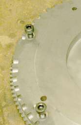
The stock opel wheel is "missing tooth" ( not missing gap), "longgap-shorttooth" in other words. Picture of the stock opel wheel:
 .
.
[Picture of stock VAG 60-2 missing tooth wheel]
![[Picture of stock VAG 60-2 missing tooth wheel]](http://vagner.jeje.je/bilder/albums/album113/Crank_60_2_wheel.jpg)
Good polarity: if you measure positive voltage (DVM, DC 200mV mode, relative to GND) when approaching a ferromagnetic object (like a wrench) to the sensor. (and negative voltage when moving away).
Missing gap - or "longtooth-shortgap"
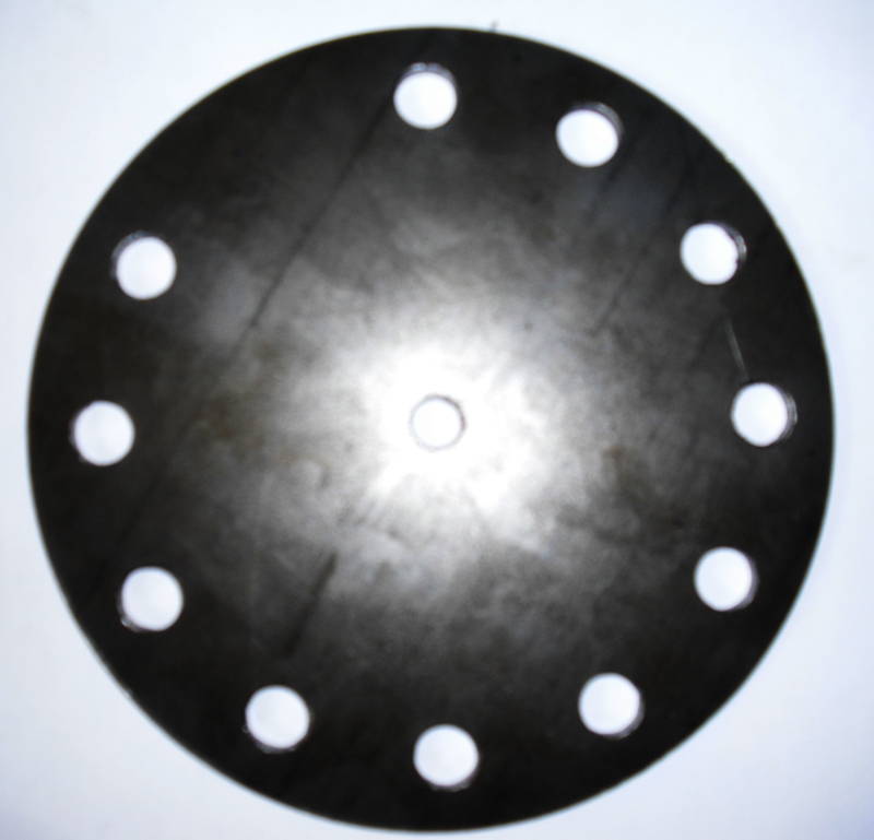
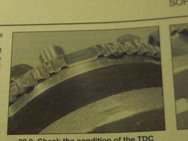
The 5mm thick steel (not stainless !) disk has drill diameter around 12mm and was actually used with Honeywell 1GT101DC HALL sensor with actual signal 18.6% high (air) and 81.4% low (steel) for normal tooth - with appr 0.8mm sensor axial distance (exact installation axial distance uncertain; the window duty obviously depends on axial distance) ; the longtooth-shortgap pattern can be seen anyway. Volvo uses similar drills (but 60-2) on the circumference of some flywheels. Another longtooth-shortgap example, see the part around the missing tooth:
Good polarity for missing gap: if you measure negative voltage (DVM, DC 200mV mode, relative to GND) when approaching a ferromagnetic object (like a wrench) to the sensor. (and positive voltage when moving away).
Naive wheel
When the depth of the missing tooth (/gap) is same as other teeth (/gaps). This means that the flux will not be same (because of "neighbor" effect) and the amplitude of the pulses will vary.
To use a naive wheel with a v3.2 or earlier, a series resistor might be required in series with c38. v3.3 already has it for more tolerance on tooth amplitude within a cycle (eg. high amplitude peak right after the missing tooth; or accentric wheel).
If the VR is connected in reverse polatirity
it will be
- 33+1.5+1.5 pattern
- instead of the correct 34+2
That is a problem, since the usual practice is applied to trigger on tooth-times > 1.5 averaged tooth-time.
(Undesirable) Effects
- complete loss of trigger
- partial loss of triggering. Unfortunately trigger is not always lost completely (sometimes depending on RPM and VBATT), which might be misleading for the inexperienced. (reason: LM1815 is trigging on the negative zero-crossing, and one of the slopes are steeper than the other..)
Indication
Currently, there is no indication on LCD or MegaTunix if the VR sensor was connected with wrong polarity (other than the wrong polarity connection might prevent triggering altogether at certain conditions).
What info could be used ?
- tooth interrupts happening, but (missing-tooth) trigger not. This is detected, but:
- lcd_engine_error_char() 'E' char is only on 2x16 LCD (someone find a place on a page on 4x20 LCD, please)
- the tooth-times for the reversed polarity VR are very characteristic: should be possible to detect directly
- storage the divided value tooth_time / ave_tooth_time in a 4 bucket histogram
- storing the tooth-times in a bit bigger (16 buckets?) histogram with some simple exponential aging (of old data. hint: RPM changes)
- storing detailed data of the last 60 (36, whatever) teeth and analize it
Waveforms
LM1815 generates the pulse on the negative-going zero crossing
Looking at http://www.picotech.com/auto/waveforms/crankshaft_sensor_inductive_running.html they probably swapped the wires.
Note that both EDIS and LM1815 triggers on the negative-going (falling) edge of the signal, around 0mV. But the [picture of Jaguar crank waveform] is measured with wires swapped.
![[picture of Jaguar crank waveform]](http://www.picotech.com/auto/waveforms/graphics/jag.gif)
However the [other waveform seems OK] for triggering on falling edge
![[other waveform seems OK]](http://www.picotech.com/auto/waveforms/graphics/jag_inj2.gif)
If the tooth-heights are non-uniform, InputTrigger/RunOut can happen.
By looking at a scope it should be pretty obvious, but everyone does not have a scope. Unfortunately polarity is often poorly documented by the manufacturer.
Around the missing tooth the polarity should look like this (but the amplitude is sick as this is a naive wheel):
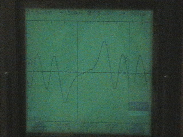
But the peaks around the missing tooth is bad. But the solution can be found at InputTrigger/MultitoothProblem.
Note: I had to connect the sensor with different polarity than on the stock ECU. pin 48 on the motronic is labeled CAS signal. And 49 CAS earth. But I had to connect 48 to gnd and 49 to signal on the genboard.
See also