As my Genboard v3.3 seems to be installed (see MembersPage/JoelZernask), I will now try to dig through the configration.
http://www.vems.hu/files/MembersPage/JoelZernask/config.txt
http://www.vems.hu/files/MembersPage/JoelZernask/tables.txt
Note that you will need to download the config.txt from the box!!! You do this by issuing Manmcd in a terminal program. The response is saved as config.txt. If you don't do this you will have to recalibrate the wbo2! No big problem but a waste of time.
In any case I have updated the config.txt file to work with firmware 1.0.36 http://media.vems.se/code/VemsMT1.0.36.zip which is a development firmware. But it significant improvements over the old production firmwares and it has been used for some time. -Jörgen
New firmware installed.
I have a feeling that the settings are still not quite right for my specs, because the primary trigger settings show 58 teeth on the trigger wheel, falling edge and the cam sync sensor also shows falling edge sign + many other things.
Here is the output of Manmcd -> http://pildid.audiclub.ee/joel/kuubik/config16032006.txt
Please review these settings.
It's supposed to be right, most of the multitooth parameters are ignored in simple trigger mode, but I would still like one of the firmware guys to take a look at the cam sensor settings as they are far from well documented.
March 23, 2006
Well, it appears that the settings are not right. After enabling the secondary trigger and switching it to falling edge, we managed to get a spark and a great BANG! out of the exhaust.
But there is something very wrong with the primary trigger settings - when cranking the rpm display panics between 0-5000 rpm. When we changed the "Constant for RPM calc" to 100, it settled down a bit. But it never shows the RPM's properly. I don't know, whether the 3 additional pins are made of some kind of wrong metal or what is the problem. Anyway I think that the fact that the ECU cannot read the RPMs correctly is the basis of all my worries. Could anyone comment on this? Has anyone experienced such an RPM miscalculation?
No RPM miscalculations like this has happened. The initial value of the constant for rpm calc was correct, change it back. There must be some type of false trigg, maybe something like the problem Miska experienced with the TDC ref sensor sensing the teeth of the flywheel as well as the trigger pins. If you have a scope available it would be nice to see how the signal looks. Double check that the right sensor location is used as well! The rpm would read insanely high if the rpm sensor location was used instead of the TDC sensor location. -Jörgen
- Yes, I also tried the RPM sensor and Yes, it showed very high numbers. But at least it was stable. The TDC sensor counting the 4 pins is obviously disturbed. Any ideas how to proceed?
Is there a configuration guide anywhere for MegaTune? I mean something that would really help to fill the cells of the graphic tables. It is not possible to configure something when you have no idea what you're doing. I'm all out of ideas... It seems to me that the simplest (or the only) way to get the car working is to install a 60-2 missing tooth trigger wheel in the front of the engine. Then I could use Ben Nesbitt's trigger settings...
March 28: As mentioned earlier you are not looking at a problem with the trigger settings. Unfortunately the sensor seem to pick up noise from the starter gear. We have recently seen some cars running Auditrigger that has had problems with that. See: http://www.vems.hu/wiki/index.php?page=MembersPage%2FMiskaPeippo%2FAudiSSix. The above is not directly applicable as the Auditrigger configuration has the TDC ref sensor connected to the secondary trigger input. That means that the resistor that should be shorted to decrease the noise acceptance is R181 instead of R182.
- The 10k pullup mentioned should be installed in the R30 (???) position on your board
- or rather 22k .. 47k and can be installed externally (between crankhome-VR signal and 5V)
April 11, 2006
Yesterday I tried to get rid of the miscalculation with a new shielded cable, applied different pullups (18k, 22k, 27k,), but the ECU still could not read the rpm correctly (rpm jumped between 0 - 45 000), and flashed a red "TRIGGER ERROR" sign on MegaTune. I tried a different sensor too - the first one quit responding all of a sudden, but that did not help either. So obviously there is something wrong with the pins on the flywheel. So now I do not see any other option than to switch to a 60-2 trigger wheel...
April 12, 2006
Today I acquired a 60-2 trigger wheel which I intend to install on the front crank pulley. Please advise me whether it is necessary to position the 60-2 trigger wheel in a certain manner, eg. missing teeth and VR sensor together at #1 TDC or first tooth (or some other tooth) and VR sensor together at #1 TDC or is this even important?
The trigger problem you have experienced is very strange, it can probably be fixed with some more investigation but I understand that you don't want to pull the engine to see if something is wrong with the triggerpins in the flywheel! With 60-2 you want the first tooth after the two missing teeth to be lined up with the triggerwheel when the engine is around 60 degrees BTDC. It is VERY important that you don't have any runout when installing the triggerwheel as the different amplitude of the signals that result from that cause the noise rejection system on the trigger input to filter out the teeth which give lower amplitude. As you have already had lots of problems I suggest that you post a picture of the 60-2 triggerwheel you aquired. There are many badly designed triggerwheels out there. -Jörgen
April 13, 2006
Here is a picture of the 60-2 wheel I have:
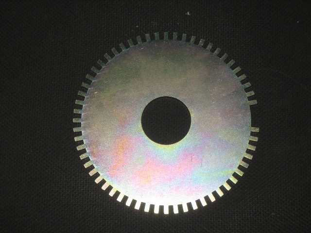
I'm almost afraid to say this, there is only so much a person can take. But the triggerwheel in the picture is very badly designed and is unlikely to work. The missing teeth section has the same depth as the normal teeth, that usually means that you get a very high amplitude signal on the last tooth after the gap. The circuit we use to filter out noise will lock onto this higher signal and will ignore a few teeth, the software in the ECU will identify that it's a trigger error and will stop injecting and stop running the ignition until the trigger is back in sync again. Triggerwheels of this type sometimes work at low rpm but cause problems at high rpm. The cars that use triggerwheels like this has very special filter designs in the ECU that is matched to compensate for the magnetical designs shortcommings. Or as an alternative they have a very simple circuit with no noise rejection. If you look at the triggerwheels in the 034 webshop you'll see examples of well designed wheels. I have asked about well designed wheels available here in Europe but have not recived answer yet.-Jörgen
April 16, 2006
OK, then I'll give this one back and order the wheel from 034's shop. This causes no harm, but a slight time delay and I stopped counting the time months ago.:)
I will pull out the gearbox next week and try to search for the cause why the sensor cannot read the 4 pins - try whether the pins magnetize and whether the sensor is in line and in a proper distance of them. I'll do this before I place the order for a new 60-2 wheel. Maybe I don't need one after all...
Trigger
Primary-VR
- NOT multitooth
- VR sensor (VR primary-trigger HW used; rising edge configured)
- do we know the polarity ?
- 4 trigger pins on the flywheel, 62BTDC each cyl
Secondary-HALL
- 1 Hall cam sync pulse overlapping the crank trigger pin occuring 62 deg before #1 piston reach TDC in it's work phase.
- Rising edge 77d BTDC - certainly this one is to be used, so configure rising edge
- Falling edge 47d BTDC. Use the other edge, not this
Here are the specs of my engine:
- 1989 Audi PT 3,6 liter 32valve V8
- firing order: 1-5-4-8-6-3-7-2
- ignition type: wasted spark
- coils: two 2*2 coil packs (Bosch 0 221 503 407)
Ignition
Cylinders firing together are:
1 5 4 8
6 3 7 2
The coil packs are connected as follows:
EC36-pin35 to Coil 1
EC36-pin33 to Coil 2
EC36-pin34 to Coil 3
EC36-pin36 to Coil 4
Therefore cylinders are wired as follows (see GenBoard/Manual/DigitalOut/Table for driver channel numbers):
Cylinders 1 & 6 to Coil 1 to EC36-pin35 drive00
Cylinders 5 & 3 to Coil 2 to EC36-pin33 drive01
Cylinders 4 & 7 to Coil 3 to EC36-pin34 drive02
Cylinders 8 & 2 to Coil 4 to EC36-pin36 drive03
- ignchmax=03 (03..00)
- IGNITION OUTPUTS TABLE: h[2]=03 02 01 00 03 02 01 00
- going from index config.ignchmax downto 0, the drive00, drive01, drive02 and drive03 will be fired, in this order.
This spark table can be used, right?

It's about right for a start but there are lots of redundant loadsites. You only need 20,30,50,70,90,105,130,150,170,190,220,255. Having 12 kPa sites from 20-100kPa will just waste time when tuning the car which is always bad. Bens current spark and fuel tables will be in the tables.txt file I'm preparing -Jörgen
Be sure to get the base timing (trigger_tooth and igntdcdelay) right.
Fuel.
Again referring to Ben Nesbitt's information, adjusted for my specs:
sequential fuel delivery for Audi 3,6 V8 PT engine
firing order: 1-5-4-8-6-3-7-2
Bosch injectors 173cc
Fuel map:

Constant for RPM calculation should be 1500 (8 cylinders), right?

Req fuel is 16,7 in my case (173cc injectors).

Here are Ben's trigger tables. How should I fill the first one on my 4 pins setup?

This one should apply to me as it is.

Is this h[0] table correct?

Communication problems
- by default (yours too, since you didn't require otherwise!) assembled v3.3 is shipped with RS232 on EC18pin14 and EC18pin15, see GenBoard/Manual/CommHardware (webshop text says same!)
After repositioning of the wires (getting it bad first?) we managed to get the only "Success!" message from the MegaTune.
- assembled and clamped v3.3 is preprogrammed. Used for testing (although the firmware could drive an engine, upgrade is recommended)
- 2. But there was still no communication between the ECU and my PC. I have downloaded and unzipped firmware 1.0.23 and MegaTune r028. Follow the instructions in the zip to upgrade firmware
3. We installed the Bray Terminal to see whether the ECU is alive. (exited from MegaTune for that time of course!). The <0>'s kept flowing and flowing endlessly.
- first, check your GND and GND5 connections !!! If you have a broken ground, or cigar-lighter groundloop to the notebook, that can result in similar
- 9600 baud: Man command
- No Hello! sign came out after Man command, just the <0>'s kept running.
- 9600 baud, but view in hex: 'A' command
- result ?
- BootLoader test: 19200 : 'S', 'p', 'v' commands
- result ? If "AVREFI1", "S", 30 or alike, you are on the track, in bootloader, just exit TerminalProgram and upload firmware without "t" option to prog.pl or megaloader (using Ew instead of Etw flags)
I suspect you maybe have started a firmware upgrade that disconnected in the middle or something. Don't worry, in the worst case powerup the ECM with the ECM's RS232 (pin2 and pin3) loopbacked, than remove the loopback and plug in the PC. Bootloader test should work now, and you can proceed from there.
Hopefully the bad connection didn't damage the max232 or something. If you disassemble the ECM, don't clamp it back until:
- remove D100 if you use powerflyback and PWM-ing GenBoard/Manual/PowerFlyback/RemoveD
- change C103 to 1nF if using secondary trigger HALL : Manual/InputTriggerHardWare/ReplaceC
- set AREF=256 BuildProcedures/SectionThree (not required but recommended)
This problem is solved - it was all caused by a wrong ECU-PC connection.