This is my collection of links that I have found helpfull and ones I have found and am not sure how to find again. As well it is also my buid diary so I know what to do next time.
Use the [Manual page] if I forgot something and search for it there.
DONE LIST
- Soldered connector to board.
- Make [Serial Cable] and connect it to your PC and Connect the other end to your board.
- Power the board. Out of fear, holding everything in my hand to feel if anything getting hot
- at (with 1A fuse) EC36 pin 25 (+8..14V)
- and (-) EC36 pin26, EC36pin5 (EC36pin21, EC36pin32). Be certain to connect at least one GND5 too. While this is not strictly necessary if no load is driven from the power-GND5 plane, we better condition everyone to always have as many GND5 connected as possible (3..4 in a production install)
- Download and open Bray terminal. Use [this link] and follow his instructions. If it works, good, if not, make sure you used a capital M in Man and com port is correct as well as your cable is built correctly.
- Download the [firmware] make sure it is the latest release.
- Downloaded and installed [winavr] so you can have programmers notepad, only need it to enable wb 02 in my make, (I dont know of another way)
- To enable wbo2, read [this page] of the manual. I opened programmers notepad, opened folder firmware/doc and opened the my_make file there. Find the part that says MY_CONF += -D WBO2 and erase the number symbol. Copy my_make into the the firmware folder and save. If you are using a different sensor other than gm compatible type ones, I think now is the time you have to use the [EasyTherm page] Didnt do it, not sure how, figure it out when/if I need to do it.
- Downloaded and installed avr studio 4, cant find the link now.
- Uploaded firmware using avr studio 4, took a bit of playing to figure out what I was doing, need to try it again while I remember and document the steps for next time.
- Downloaded and installed [MegaTune] run it with the board connected, seems to communicate.
- Soldering stuff on, start with the FETs, easy to do and good to warm up on before tackling the surface mounted stuff (which, after you figure it out, is easy enough). FETS can go on top or bottom, just as long as they have something aluminum to clamp to for cooling. I think maybe the Alubus case would require it to run on the bottom or you would have to modify stuff. BUT I am making my own case to match my Honda ecu connector so I put mine on the top. Plus I am trying to make the case as skinny as possible so it will squeeze into the slot I have for it. Top or bottom, if looking at the side with the writing, I called the pin on my left pin1. I made sure that my pin 1 is closest to the EC 36 connectors. [
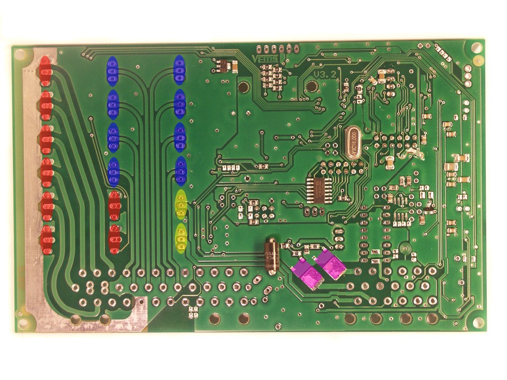 This picture] shows orienatation of all the fets including the dpak (purple) as viewed on the bottom of the board. Yellow is wbo2 with channel 1 being closest to the EC 36, blue is injectors, red ignition IGBT's.
- Because I am using LS1 smart coils, I omitted IGBT's and placed a jumper wire in its place between each of the first 2 holes, connecting the AVR pins right to the coil trigger. If it works, I should add it to the IgnitionPage. Some readings I have from a vehicle running these coils can be found on my MembersPage/EricN .
- Not sure if this next one is important, it seemed to be pretty obscure to find but if using a Hall sensor, below Ec36 pins 28 and 29 there are 2 smd pads