TODO
I am keeping my working conversation at the top of this page:
P259 fried due to output shorted to +12V U20 chip
- take note of the old chip direction. (perhaps note+photo)
- Cut legs
- remove old chip and legs
- no need to tin all pads
- set new chip. Solder 1..2 legs first
- verify position. Solder rest, one-at-a-time.
story of the blow-up:
The chip was damaged during cranking up after a long time with a broken engine. When I turned the key on the FP relay was cycling very quickly....maybe at 30hz or more. I thought the relay was bad, so I jumped the contacts to power the pump. This circuit also powers the injectors and some sensors on the engine(I reused the old edlebrock pro-flo harness and it was wired this way). I did this and had my brother turn on the key to start the engine. About 5 seconds after I jumpered and 2 seconds after he turned the key on, I heard a pop in the Genboard. Removal showed a nut fell from the IGB heat sink and was loose. It also showed the U20 has a small(maybe 1.5mm) chip blown from the top and smells like a plastic fire. My assumtion is that the nut caused a shorting of the chip. I dont think shorting the relay caused the chip failure from what I can tell of the genboard schematic...but I could be wrong.
Due to the problems listed below in "Current Updates" I am going to be upgrading my ignition system a little. I really do not think that it is a trigger problem because of the clean RPM line shown on the datalogs and while watching megatune. The problem does get worse when the engine warms up, but I have found it is load dependent after more testing. It takes less load to cause the condition when hot, but it is still load dependent. After talking to several people about forced induction engines with single coil ignition, it became clear that I need more spark power in my system. I bought a large capacitive discharge ignition (CDI) amp to strengthen my spark delivery and have a question
MembersPage/ChrisGerhardt/ExternalIgnitionAmplifier
Clean trigger signal. The input trigger circuit is not set up as on GenBoard/Manual/InputTriggerHardWare since those instructions didn't exist at the time when engine was first started.
However RPM shows way too high at cranking, not good. The trigger signal HW setup needs improvement.
Rather good trigger since v2,
- shielded cable (shield connected only on one end)
- cap from HALL supply close to HALL sensor
To set up GenBoard/Manual/InputTriggerHardWare, the board would be have to be unclamped, and take out of alubos (the onboard MAP sensor is in the way, so removing just endplate wouldn't work in this case)
There is a simpler method that is worth to try in this case:
- add a 10nF cap between HALL signal and EC36-pin26 GND, close to the board (max 25 cm from the EC36 connector),
- add a 4k7 (or max 10k) pullup resistor between HALL signal and 5V HALL supply This can be at the HALL sensor, or at the same place you added the new cap (above) - where convenient.
Parts are in the GenBoard/VerThree/RescueKit. Keep track of parts in rescue2 when you use some. If you make a small patch in the loom, you might want to use throughole parts (not in the rescue kit, but very common parts in old radios) or some carrier (a 1x1cm corner of an old prototype PCB; or embed into glue after soldering and test).
There is about 80% chance that this will give good result in your case so box need not be opened for the complete setup as on GenBoard/Manual/InputTriggerHardWare way.
Problem Found:
Jorgen noticed this on my log and it became very clear. You can see around the 21.1 sec mark on the log below that fuel is cut from ~18 down to ~3mS PW when TPS changed 10%. This was caused by my fuel cut settings. The problem is that this should not be possible above a certain throttle position in my opinion. It gives people the opportunity to blow their engine if they make a wrong setting......of course many other things with tuning could cause this too.....just be aware of the situation
Current Updates
4/17/05
I am having some tuning issues since I went to open exhaust with downpipe only. I had not had the problem with exhaust, but it does not mean it was not there since I did not push it real hard until opening up the exhaust. What I am seeing is that when I am in the throttle hard and above 5000 RPM or so, the engine basically dies as if it has lost fire for a second. I let out and get back in it and it revs back up. It is so repeatable I think it could be a config. issue so if you all could look that would be great. AFR and EGT are still looking good at those points. Below are my files and a datalog:
http://www.vems.hu/files/ChrisGerhardt/datalog01.zip
http://www.vems.hu/files/ChrisGerhardt/etc_chris_config_r006.zip
Let me know......Chris
1/30/05
The engine is back together and in the truck. I am currently waiting on a new radiator to get here so I can start the engine. I would also like to get the headers and piping ceramic coated to keep temps down. I hope to be running again in a few weeks.
9/16/04
BAD NEWS - The engine in the S-10 has died an ugly death. After getting the engine out of the truck, it looks like my block was not cleaned properly before assembly. I paid for cleaning and did not do it myself......hard lesson learned. The main bearings are completly gone down to the steel shell on one and in the copper on others. It looks like a huge amount of trash went through. Everything else looks to be okay, but the engine will be out for several months to have the crank turned and to wait on parts and assembly. More later......
9/6/04 - I got around to trying to reenable the ego control and was going to update firmware for the ego changes a week or so ago. I found that there are about 25 new variables added to config.txt in the new code. Can someone point me to details about these variables? Maybe you can list the variables....
hint: those that have channel in the name are GenBoard/Manual/DigitalOut type, disable them with ...channel=FF.
The input thresholds (typically min and max variables) will not care than, FF is fine there. Some other safe values:
als_ignretard=00
als_rich=00
knock_conf=00
knock_max_retard=00
knock_advance_step=00
knock_retard_step=00
Can you find some pages for these ? (we'll fill out in more details).
More test today 08/15/04:
I hooked up a set of lights to the injector plugs and it became very obvious I have a problem. injectors 5,6,7 are turning on with the fuel pump and injector 8 is not doing anything. I have checked the wiring and can not find anything that would suggest a short or bad wiring. (note: turned out that 2 FETdrivers were missing).
I also tryed the flyback test, but I am not sure what voltage the diodes are that Marcell sent me.
Do you remember,Marcell? Not sure, I think 20V. But do they have 6V8 text on them? If so, they are 6.8V diodes. Otherwise 20V. But how did you solder if you were not sure of the type ? I hope at least the normal (well, fast) 0.7V diodes are soldered in the right direction.
What I see is that when I connect the (-) of the supply to the inj common(flyback pin of EC) and the (+) of the supply with 47ohm resistor to any of the injector pins of the EC, the voltage drops from 11.71VDC to 11.53VDC (0.18V / 47 Ohm = 3.8 mA). I expected to see no drop if the diode was the 20V and a significant drop if it was the 6.8V. Please let me know your thoughts..... I expected the same. They are likely 20V.
My current config.txt, tables.txt, and my_make can be found here:
http://www.vems.hu/files/ChrisGerhardt/etc_chris_config_r006.zip
I'd rethink these:\n�1�
I'd try injopen=20, battfac=10, injocfuel=0E
Although hard to suggest anything, as you provided no info about your flyback voltage.
Okay, I can change those values. What would you want to know about flyback voltage? I can test, but I dont know what I would be testing for. My flyback is hooked up just as in Fero and Tonci's diagrams directly to injector VBatt.
The Beginning....
Well, I got my GenBoard V2.2 in mid October from Marcell Gal after he lured me to the project. I basically started from a point of knowing absolutely nothing about programming or working with any of the software involved with the AVR project.
First thing I did was download all of the software that I needed to work with the AVR. This included Active Perl, Win AVR package, CVS software, Megatune software, and all of the information I could find about the original MS. The other thing I did that I would highly recommend is to print a full version of the Megamanual. While some parts do not apply, most can be related.
Next came trying to get the firmware downloaded. I had multiple problems, but finally got a snapshot from MembersPage/MichaelKristensen's site available from LinksPage . I went ahead and downloaded it so I could at least have something to work with. I went ahead and used it, but later had to download the latest firmware from CVS. MembersPage/DanaScott has a nice executable file that will automatically get the latest firmware. If you contact him, I am sure he will share. First check GenBoard/FirmWare/CVSUsage page, since it has the very same instructions that Dana has in the script, and it might contain link to the script too. It is nice for newbies like me.
Next I decided to make up a pig tale for my DB37 that I could use to attatch to my existing harness. I had to use the MSAVR Schematic along with the Existing Edelbrock system schematic to figure out exactly what I needed. I am going to reuse all the Edelbrock relays and fuses since they are effectively the same as what the original MS drawing shows. I will also try to get a schematic drawn up in Microsoft Visio so those later can use it.
The LCD and Keyboard......what a pain...for me anyway. I was able to find a plug at a electronics supply store that went from a 10 pin out like the one on MSAVR to a DB9 connector. I used this for the LCD connect output and spliced in a PS2 Keyboard plug I got at the local computer shop. I finally got it working after finding I had a firmware problem.
A schematic which is on the LCDConnect page of what I did:
http://www.squirrelpf.com/msavr/index.php?page=BuildProcedures%2FLCDconnect
The schematic looks OK, though a bit hard to see which line is which with the unnecessarily long parallel wires. (Marcell Gal).
Installation:
I got the Genboard installed in my truck this weekend 02/13/04. I used the schematic from VehicleWiring page with a few small changes. The existing harness has a single 10A fuse for injector power which I left in place. I also grounded the analog and digital grounds to two different points after reading that electrical noise can cause sensor signal problems. Sensors and TPS all look good. I got TPS min and max set using megatune and inserting values into my config.txt. I did have some issues getting my Hall Distributor to work. I found that the Hall sensor does not output voltage on the signal lead. Instead it shorts to ground when not triggered and opens to ground when the shutter wheel passes through. I can across a diagram on the MSNS site that should work for this sensor. I will add that the pins ARE NOT CORRECT for MSAVR, but the schematic gives you the right idea. ALSO, THIS ARRANGEMENT IS NOT IDEAL. BETTER TO SWITCH THE HALLoutput to the CATHODE of optocoupler, see below

02/16/04 Well, I found that this Hall sensor configuration does work. As suggested by Marcell, I will change the resistor value to 470 ohm to make things easier on the Hall Sensor. It does appear that the signal is being recieved accurately to the AVR since I can use a drill with my newly assembled spare distributor and get good RPM values in megatune.
02/16/04 AHHHHH!!!! SMOKE!!!!!!!!!!
Yep that is right I smoked a trace. After some research it was two problems that appear to have caused it. First, I used steel standoffs to mount the board in my aluminum case. I did not notice that this caused a ground short on the injector output. I also had a string of solder from D17 to R25. When I got the V+ flyback circuit hooked to power, it went straight to ground across the solder and through the mounting stand off. This fryed some traces, but they can be repaired with jumper wires. Lesson learned: DO NOT USE STEEL STAND OFFS TO A METALLIC CASE!!!!
02/16/04 I found that the ignition module fires at falling edge and will not control dwell so Genboard will handle that. (ign_out=71 in most recent Firmware)
2/24/04
I found that with the above configuration on the igntion trigger I get alot of noise on cranking on the trigger. After talking to Marcell and some of the original MS people, I decided to try another configuration. It will require some modification of the circuit, but not too much. Remove of D12 and shorting of D10 with 100 ohm resistor are the first things to do. After that, take R42 to VCC(5V). I still see that I am getting some noise on the trigger so some more mods are to come....
2/26/04
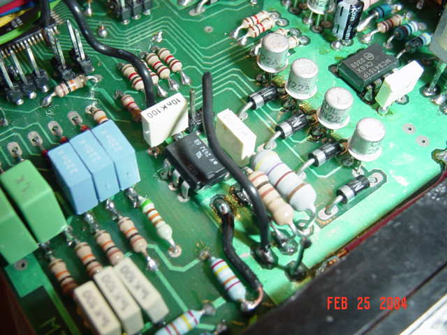
Today I added a dedicated, sheilded cable for the hall trigger and also added a 1uF cap across the hall sensor leads at the hall sensor. I also added a 4.7nF cap in parallel with C20 for more noise suppression. The last thing I did was try to get the ground cleaned up a little while cranking. I did this by added a 1 guage ground strap from the starter to the frame. I can not tell you which modification made the difference, but today my trigger is very clean. Below is the final schematic that I ended up with:
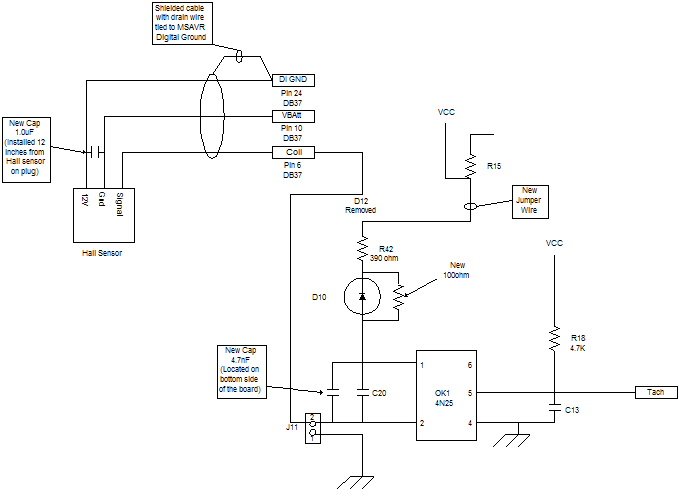
Below is also a picture of the modification. The D12 traces became useful after removed to get 5VDC to optocoupler and to get the other side of opto out to the Hall sensor. We'll see how it works.
With this change, I had to also make a change in the igntion trigger configuration since the action of the opto was effectively reversed. If the rising edge on the HALLoutput (if pulled-up) gives even spaced pulses (because tooth1 is narrower), the rising edge of IC3 must be used with this setup (trigger=FF). When the signal goes high, the optocoupler internal LED turns off, the output will rise too (non-inverting setup).
the crank_ic3dis variable is replaced by
uint8_t primary_trigger; // trigger1, bit0 0:falling/1:rising, bit1 0:toothwheel/1:coil, bit2 0:no filtering/1:filtering
if you had trigger=FE (falling-edge, coil type) you likely want
primary_trigger=FE
(falling-edge, coil type, filtering enabled)
secondary_trigger=FF
will disable secondary trigger (which you don't need).
IT'S ALIVE!!!!
It is official! Feb. 27 2004, the engine is running on on MSAVR. After some sorting out of the ign_tdcdelay value I have the timing set to 18 degrees initial and cranking which the engine seems to like very well. A timing light confirms that the ignition trigger and output are clean and precise. I feel very good about this.
I also found that I was getting alot of backfiring through the exhaust. Marcell traced this back to my ignition fuel cut values. It looks like the real problem was with my tpsdq value. I had accidentally set it to tpsdq=50 which is 80 percent fuel cut. This looks to be causing an excessively lean mixture that is not burning but being pumped into the exhaust. When the engine comes out of decel fuel cut and begins fueling again it begins to fire. At this point the raw fuel in the exhaust ignites. This is just theory right now, but I will test it out as soon as possible to let everyone know.
3/1/04 Went out today to test the theory. That unfortunately did not completely solve the problem. It did help. I think the other problem is in ego control. Bad news is that my fuel pump has crapped its guts out so I will have to get anther on the way. I will resume testing in a couple days and post the results.
3/5/04 Got the fuel sytem sorted out today and actually got to go for a test drive. I did not have anyone to help tune so I was not able to make any boost. The engine is still doing some backfiring in the low RPM range. For some reason pulse is reduce in the 2000 RPM range. I have turned off ego control so I am not quiet sure of the problem. I am sure more testing will reveal it. The engine runs good once it is under some load and above 2000 RPM. The VE tables were very close for lower RPM operation. When the engine starts to rev it make boost pretty quick and I thought I started hearing some detonation, so I had to take it to the house. I will test some more soon and report back. After some thought, it became evident that the noise was the wastegate valve cracking open to maintian boost. I have now made a wastegate muffler to remedy that.
Tuning updates
03/20/04
I did alot more tuning today and the engine is running very good overall. Holy Crap, this thing is going to be fast!!!
Chris, you were right with the ign outage in a small RPM-window depending on ign_tdcdelay, ignadvadvance and dwell settings. A line was commented out at some debugging session, and somehow left that way. You'll need to cvs update.
4/3/04
More problems: I started the engine today to try to fix a nagging oil leak and found it missing on one injector channel. After some testing I found that a TPS short was causing low voltage operation and shut down. It seems that this caused IC3 to loose its mind and start doubling frequency on channel 1 output. I replaced this chip and the missing problem did not go away. While trying to find the problem I shorted the new chip and smoked it so I am waiting on parts to test some more.
I also was trying to setup my other laptop for genboard work and had some problems with active perl. It seems that it installed "c:\perl\bin" in the path instead of "c:\perl\bin" The leading slash has to be removed and then the machine rebooted to fix this.
5/5/04
Well, genboard has been up and running again for a couple weeks. I am having some problems tuning the overrun fuel cut and overrun fuel resume. It appears that with the automatic transmission and high stall convertor, there is some issue if the two variables are too close. Basically when fuel resume point is crossed after the fuel cut, the engine RPM actually goes up because of the viscous coupling of the torque convertor. This then induces fuel cut again when RPM rises to the fuel cut point. You can see how the engine basically sticks in the control loop at this point until the truck slows down enough to let the engin idle down. I also plan on doing fine tuning and high RPM j table tuning in the next day or two. I will report back with my results.
5/25/04
I fixed the overrun fuel control problem by raising the RPM and putting more RPM between the cut and resume points. I did find that my wastegate was not near large enough and probably places poorly so the truck is torn down again for new 50mm wastegate and some header fixes and modifications for clearance issues. Here is the latest piping: 
5/30/04
After a generous offer from Marcell, I placed my order today for a V3.1 GenBoard. I have been thinking of doing this, but funds have been in short supply. I will be making the change over to V3.1 over then next month or two. I will have to build a new case and connector. I am not in a huge hurry since the engine is running great on V2.2 V3.1 will give me many more options and tunability when I start trying to move up the boost and HP.
7/4/04
I got all my parts from Marcell and now have Genboard V3.1 communicating via megatune and bray terminal. I will begin more testing and output wiring soon.
8/11/04
Well I finally got V3.1 installed in the truck to day well enough to do some testing. I am getting good readings on all sensors and trigger also looks good. I went ahead and tryed to crank the engine before testing outputs of injector FET's and ignition IGBT, but it did not start. I will do some testing to find the culprit in a few days. Since I smell fuel, I suspect it is in the ignition config or hardware.
9/1/04
The engine is now running on V3.1 pretty good. I need to do some work on the VE and lambda tables since I am finding that this engine does not like anything leaner than 13.5:1 AFR at cruise speeds. It is likely do to the large cam and low compression. I have done a few short WOT runs and it feels promising. I am having some problems with getting boost to the engine with my current bonnet so there is yet another bit of fabrication to be done. I may try to go ahead and run the engine at the track like it is so I can see what kind of difference a bonnet change will make.
Night Rider O2 Display Schematic:
I found a cool schematic for a "Night Rider" bar graph dash display for O2 monitoring. I think I will give this a try when I get some free time.....like that will ever happen. If anyone else is interested, the like below will take you there.
http://www.sonic.net/~mikebr/efi/pdfs/bargraph_d.pdf
Discussion:
Q: I seem to be having problems with the engine dying for no apparent reason while driving down the road. I also see that once in a while the engine begins to run rough and will not communicate with mt. It has been suggested that a Watchdog in the code would help this. It has also been suggest that I add caps to power. Any thoughts on this?
Is anything heating up ?
Any chance you can take an rs232 snapshot of what the mdkffmdfff says ? (only works with BENCHMARK defined).
You could try v3.1 (as I remember you have no spare v2.2) with the same config. If the v2.2 didn't do the same earlier (with same firmware?), I'd think that some capacitor didn't like the heat. v2.2 had some eletrolitic caps that don't like heat (these were eliminated on v3.x).
I almost forgot: the very first thing you have to check if flash is exactly the same as you uploaded earlier. (Et flagword to prog.pl without w so it does not overwrite, and if there is any mismatch error, read back the whole flash content with ISP or avrprog (as prog.pl does not have this function IIRC) before overwriting and send us both so we can check what changed.).
V3.1 Questions:
Setting up hall:
<Dave23_>you need to solder sj1 and sj2 short (solder blob) and solder a pullup resistor at r30
<Dave23_>pullup can be in range of 1..10k, just what you have lying around
Q: I am only seeing 50mV between Pump (-) and GND. The wiki page says to check voltage divider resistors......which ones are they?
WBO2 related useful info should go to GenBoard/Manual/WBSensor
The values depend on config, wbo2_abs_limit and ramp values; You should always measure between +14V and output, as measuring to GND will give you useless info unless you have a pullup resistor (or the heater in place).
Q: C88 on the hall circuit is listed as 1uF in the 1210 size. I only have the smaller 0805 in 1uF and 10uF in the 1210 from the rescue kits. What is the best choice? I know I had to add a cap on V2.2 for noise suppression so I assume the cap value is not too strict.
- 10uF 1210 size 35V is optimal for VR type input
- SJ1 optimal for HALL type: so you can short C88. This will effectively give the same circuit that you used for your v2.2.
Please move the essence to the relevant page (btw: why not ask there?) Okay.....when I get a few free minutes....its been busy here.