This is an Audi 200/20V with 3b engine
The follwing modifications have been made:
Turbo: Garret 3071, AR 0,63, 100mm inlet HF
Injector: blue bosch 470ccm
fuel pressure regulator: stock 3b maybe want to swap to 7a
Ignition: 5 active TFSI coils
compression: 8.6 - 1
exhaust: RS2 manifold + 3 inch exhaust
hall sensor: cam hall sensor as ADU(adjustable camwheel)
crankwheel VR sensor(engine speed): 60-2 sensor
MAT Sensor: PTC type, change to NTC planned
A Motronic55 install might save some time making a harness, but you must always verify the harness reasonably carefully.
This involves
- measurement of all used pins
- mostly DVM ohm-mode
- sometimes voltage mode
- visual inspection
- the injector part of the harness receives much heat. Insulation might be worn. It's better to fix ASAP, than to risk engine damage.
Make your own page for your measurements like MembersPage/TormasiAudiAan, using this as a template. Steps:
- add your measurements
- save your memberspage
- save from time to time, don't risk losing many hours of edits. You can also keep snapshot of unsaved changes in a local file, especially if the browser you use is abbreviated as msie.
- close this page (without saving)
Documents and files to use
This is the most important docs, so you know pinout and function mapping. In VemsTune you will see names like EC36pin10 while you have it wired to some motronic pin. While you do the measurements, write the measured value and the pin you used, and any notes you think appropriateConfig and tables
Find the quick method on VemsTune/QuickStartAudi. For boxes sent out after 2008-07-31 check the "Cam HALL Inv." checkbox in the "Upload Config Files" step.
- check the 727cc checkbox if you have 727cc injectors
- the "AAN" and "Factory Inj" is probably the same as in the "Basic config" and "Basic Tables" (files), so they theoretically make no difference
- after you upload config, dump the config with "download config" menu, to get a "unified" config and tables for later use, and possible reports (it can be used to verify that the proper option were selected for your setup).
This quick method is useful because the config is split to basic, trigger, injector and ignout sections to support combinations of 3B and AAN engines with different injectors, with or without cam-HALL inverter and different ignition output setups.
Firmware and tuningsoftware
- [VemsTune]
- (TODO: Provide link to "vemscfg" config file here )
Sensor measurements
- Temperature calibration are available when updating firmware through VemsTune.
- Coolant: NTC type 1900_256 or 2063_256 is a very good starting point when nonstandard NTC sensor is used with weak 2700 Ohm internall pullup
- MAT: PTC type 260_425 is a good starting point when the factory PTC type MAT sensor is used with the default strong 430 Ohm pullup (for some reason the 260_425 was more precise for us than 260_430)
Or make your own through EasyTherm. Measure sensor resistance against AANpin30.
- ... Ohm between 44 and 30 (MAT)
- ... Ohm between 45 and 30 (CLT)
Injectors and idle-air output measurements
Measure injector and idle air pins against AANpin37 (that is the flyback pin, same function as EC36pin23 in standard VEMS docs)
- inj cyl1, AANpin17, EC36-pin20, INJ-D
- inj cyl2, AANpin16, EC36-pin8, INJ-C
- inj cyl3, AANpin15, EC36-pin9, INJ-E
- inj cyl4, AANpin35, EC36-pin19, INJ-B
- inj cyl5, AANpin34, EC36-pin7, INJ-A
The firing order is 1-2-4-5-3 and it's ok to shift this table, it keeps the injector firing order.
While injector connectors are disconnected (and ignition output stage also): after applying ECU power (ignition on),
- temporarily raise (VT / outputs / fuelpump) "pump on after powerup" to 63 seconds
- after powerup, measure that injectors and ignitions are not active even while fuelpump is on. Injector: voltage measured between 2 pins of same connector (<3V is inactive; if >3V even with a 510 Ohm load applied, that's considered active). Ign: voltage measured between GND and output stage ign-control-signal (not High-Voltage wires !).
- Usually fuelpump can be heard. Otherwise watch fuelpump_on flag in VT, and/or use a 2nd DVM.
- repeat for all injectors and ignition channels (remember that fuelpump will be on for "only 63 seconds" after powerup, so will need to powerup a couple of times to measure all)
- when verified all: reset "pump on after powerup" to appr. 3.5 seconds
Ignition outputs
Check the spreadsheet (link above) with all the pins.
( TODO: Very important. This changed to different pins on the ECU board. Config can not be re-used easily from older ECUs. When, after what date? which serial nrs are affected? )
- cyl1 AANpin1, EC18pin11 StepperD (0x66) mdn03
- cyl2 AANpin2, EC18pin5 StepperC (0x56) mdn02
- cyl4 AANpin20, EC18pin10 StepperB (0x46) mdn01
- cyl5 AANpin21, EC18pin4 StepperA (0x36) mdn00
- cyl3 AANpin23, EC36pin11 ignch4 (0x40) mdn04
Very old Motronic harnesses and ECU have swapped cylinder 1 and 3, which are AANpin1 and AANpin23, only very few were made this way.
If in doubt, just remove sparkplug high-voltage wires (easier if 1 at a time). make a small 1mm gap to ground (with a wire or a sparkplug) and used the spark output test function from within the tuning software to see if cylinders fire in the right order. It is recommended to do this for all 5 cylinders as an end-to-end test.
Grounds
Measure that grounds are strongly (max 0.1 Ohm) connected inside the VEMS ECU.
- AANpin10
- AANpin19
- AANpin24
- AANpin30 sensor ground
- AANpin48 trigger ground
Measure ECU pins: verify that all the above grounds are connected inside the ECU.
Measure that first 3 are connected in the harness. AANpin30 (sensor ground) and AANpin48 trigger ground are likely not connected inside the harness.
Trigger
The secondary trigger crankhome-VR MUST BE reversed. Can be done in the connector on the firewall.
Measure trigger resistance against AANpin48.
- ... Ohm between 49 and 48 (135 cranktooth-VR primary trigger)
- ... Ohm between 47 and 48 (crankhome-VR secondary trigger)
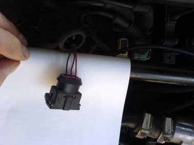
Reversing crankhome-VR polarity
- Disconnect the crankhome-VR secondary trigger (3 pin AMP connector at the firewall. Was black in our AAN harness). In the female connector:
- measure with DVM which of the 3 pins go to motronic AAN pin48 (this is trigger GND)
- measure with DVM which of the 3 pins go to motronic AAN pin47 (crankhome-VR secondary trigger. The 3B engine-harness pinout is different: 3Bpin49 !!!)
- measure resistance between pin 1 and 2 in the 3pin male connector (of the sensor). You should get the same Ohm as above (eg. 980 Ohm, or 1010 Ohm or around that)
- swap the 2 wires in the female connector (red and violet in our case)
- if you cannot pull out the receptacles, than you need to cut, blank, solder and insulate
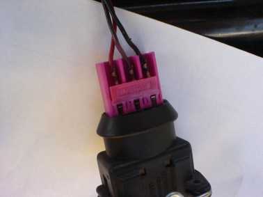
- mate the crankhome-VR secondary trigger 3pin connector (male in the female :-)
- do the measurement in the motronic pins, ... Ohm between 47 and 48 : it should still be the same (the ohm measurement is polarity independent)
Location of the trigger plug:
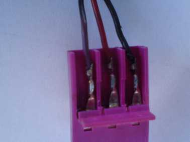
Wiring crank home normal:
Swap the red and violet wire:
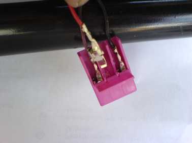
The wire is swapped:
HALL signal
- ... V between pin8 and pin 30 (this needs ECU plugged in and ignition on so the ECU outputs +5V to pin12)
- changes between 0 and 4..5V as the engine rotates (push the car in gear5)
WBO2 on SSC5 male standard applies to both Audi AAN and 3B (also to BMW):
- pin1 nernst,WBO2 pin 1
- pin2 WBO2 pin 3 (use a 5A fuse from +12V supply wire)
- pin3 heater(-),WBO2 pin 4
- pin4 pump(-),WBO2 pin 5
- pin5 pump(+),WBO2 pin 6
OBSOLETE SSC4 male WBO2. was used before 2007-08 (now SSC5 is used)
- pin1 nernst,WBO2 pin 1
- pin2 pump(-),WBO2 pin 5
- pin3 pump(+),WBO2 pin 6
- pin4 heater(-),WBO2 pin 4
- Remember that WBO2 pin 3 must get heater+ from a 5A fuse from +12V supply wire ! The WBO2 heater+ does not come from the ECU (only the WBO2 heater-)
AAN ECU extra connector pins:
SSC6 feemale
- pin1 mcp3208 pin6,ch5
- pin2 mcp3208 pin7,ch6
- pin3 mcp3208 pin8,ch7
- pin4 EC36 pin 34 (power out)
- pin5 EC36 pin 36 (power out)
- pin6 GND
Extra Econoseal 10 pin connector
- Documented here : [EC10 pinout]
- ( TODO: Copy information on that pdf/doc to this page, serial port/bluetooth, etc info )
3B ECU extra connector pins: AS YOU LIKE
3B note: motronic55, pin1 is EC18pin11 (stepper-D), see pinout
IF YOU USE DISTRIBUTOR and one ignition output to control spark for all 5 cylinders, you must limit dwell in config. To allow high spark energy at 1.5+ bar boost especially above 7500 RPM, distributorless ignition (or CDI) is needed.
SSC6 feemale for 3B... unspecified
- pin1
- pin2
- pin3
- pin4
- pin5
- pin6 GND (use pin6 for ground if you want ground at all. You can also require that pin6 is an analog input or an output)
Note that there is NO best, one-pinout fits all pinout for 3B. The 3B extra pinout is made as requested in the order note.
- Sometimes more ignouts (power or logiclevel) are desirable
- other times more analog inputs.
eg.
- 4 outputs and 2 analog inputs might be a good choice (allows 5coil setup).
- 1 ground, 3 inputs, and 2 outputs allows distributorless ignition (not an everyday setup, but it works)
- cyl1 driven by factory coil (motronic55 pin 1 and the factory ignition power-output stage and coil)
- cyl2,5 and cyl3,4 driven by a 2x2 wastedspark ignmodule (logiclevel input active coil or power input passive coil like the durable [Bosch motorsport wasted spark coil] - we used the 2x2 model but the 3x2 is also suitable)
In short: when ordering 3B, in the order comment, you can just write
- "on the SSC6 please make 2 (3,4,5, whatever you like) logiclevel outputs for active coils"
- "on the SSC6 please make 2 (3,4,5, whatever you like) power outputs for passive coils"
The more pins used for ignition output, the less of the SSC6 can be analog inputs (useful for ALS, shiftcut, launch,... activation inputs).
When requesting less than 5 channels (2-4) on the SSC6, the 1 pin through the motronic55 is by default logiclevel for active ignition coil (the factory firewall-mounted POS Power Output Stage together with the passive coil is equivalent to a logiclevel coil). As always, of course you can explicitely request power output for the motronic55 ignition pin for passive ignition coil when ordering.
Note that the [VAG active COP] did not fit mechanically into our 1989'3B cylinder head. Might be a good idea to try before relying on it.