I want to turbocharge my BMW 518i E28 M10 engine by using VEMS
Installation specific
- connector (if going with PlugAndPlay setup instead of Econoseal connectors). The econoseal-connector based install looks much cleaner (avoiding wire jungle, and less work), and generally recommended over the plug and pray way.
- wiring - whatiswhat. see PlugAndPlayJetronic, it saves some time with the wiring (not only for PlugAndPlay but for the econoseal install as well). Try to find other sources and measure yourself too for verification.
- tables: OnlineCourse/AlienIgnitionLogging is theoretically possible, but requires more experience or experimentation than the rest of the install. I think better tables can be found faster from the web, maybe from others from MembersPage.
Trigger/ignition plan:
I keep distributor only for distribution. I use Hall sensor on crank as a trigger input for the VEMS.
Q: So actually I have to lock the plate in the distributor and remove the vacuumline in order to lock the vacuumadvance and let the distributor only distribute the spark?
A: With the distributor used only for spark distribution, and not timing advance, none of what you described is necessary. The poles in the rotor cap are fixed, that is all that matters for spark distribution.
Q: Do I need a triggerwheel or can I just bolt on two magnets 180° separate on the standardcrankwheel?
A: With many auxiliary belts (air conditioner, servo steering, ..) this can be a problem to fit correctly. The main concern is that it must be rock solid and accurate, and be appropriate for the sensor you will use with the trigger solution. With a good Hall trigger (Honeywell GT1 is recommended) you don't have to use magnets, two slots or fields in a ferrous material is all that is needed and can be fastened in many ways depending on how the stock crank pulley is designed. In this day and age of cheap digital cameras, pictures still speak more than a thousand words, so get some snapshots.
OK here is a pic from the crankpulley:
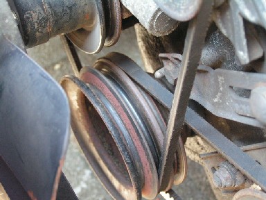
TODO: fabricate trigger setup with Hall sensor on original crankpulley
ITEMS TO BUY:
- Genboard v3.3
- injector FET 6x
- WBO2 FET 1x
- ignition IGBT 5x
- mapsensor 2.5 bar
- idle stepper moter driver
- econoseal PCB connector 36 + 18
- econoseal harness 36 + 18
- CNC case
- LCD
- tempsensors 2x
- WBO2 connector + sensor
I recommend buying a pre-assembled Genboard to avoid this part of the project, but in case you feel confident with electronics and like the idea of saving some money - then go ahead. I would advice you to fully populate the board with as many fuel injector FETs and ignition IGBTs as you can afford - they can be used for a lot of other things and the minimum I'd recommend is 6xFET + 5xIGBT. That allows you to run a direct-fire (distributorless) setup in the future.
Q: What about TPS? Should I look for a TPS with WOT switch and potentiometer?
A: A true potentiometer type TPS is recommended for full use and control. A WOT switch is not much use, it can be used to raise boost target with BoostControl. In MegaTune you configure and calibrate the maximum and minimum TPS values (idle and WOT). You can also set the idle threshold value (1-2%).
Only in some cases do you really need to know the exact position of the throttle plate. You can use a resistor grid with the stock "on/off" TPS, to make three distinct positions/resistance values (idle, in between, WOT). It has worked really well on this car: MembersPage/MattiasSandgren/BmwSevenTwentyEight
The basic idea is to connect the TPS In (EC36-1) to a pullup resistor towards +5V (EC36-28) and a pulldown resistor towards GND. The pullup resistor is shorted by the WOT switch (raising TPS In to +5V) and the pulldown grounds the signal. To protect from a short (should never happen), connect a resistor between GND and the pullup resistor and Idle-switch so that there is a minium resistance to be met between +5V and GND at all times. Use 1K resistors, or similar size.
[A drawing of the circuit used with the stock TPS]
![[A drawing of the circuit used with the stock TPS]](http://www.vems.hu/files/Marteleur%20Tim/TPS3.JPG)
Q: How will I control coldstart issues?
- Afterstart enrichment. Afterstart enrichment has a cold value (config.awev=1D for +29% at -40C) and a scaler (config.awev_temp_scaling=A0 for 160/256 * awev) so it's downscaled at high temps (above 71C)
- warmup enrichment
- To avoid having too much air enter the engine when it has warmed up, get a bipolar stepper valve or an idle air solenoid from a Motronic car and do like this: MembersPage/GergelyLezsak/IdleControl (it's still an experimental setup, isn't it?) GenBoard/Manual/Config/IdleControl
Q: should I use the solenoid type or the mechanical type from the Ljet? What is the easiest and most reliable?
[Picture of Auxiliary air valve (usually L & K-jetronic)]
![[Picture of Auxiliary air valve (usually L & K-jetronic)]](http://www.vems.hu/files/Marteleur%20Tim/idlecontrol1.JPG)
or this one from the motronic
![[Idle air solenoid]](http://www.vems.hu/files/Marteleur%20Tim/idlecontrol2.JPG)
A: I'd use the Motronic to get the most control, it's a bit experimental but it would be neat if you could get it working properly. Gergely is working with this one on his BMW. You can find Gergelys work here: MembersPage/GergelyLezsak/IdleControl
If you want to avoid the guesswork you can use the older bi-metal "Auxiliary air valve", it does a good and reliable job and is activated as the "fast idle" valve, and shuts off at a specific temperature.
Q: When I use the Auxiliary air valve how will the electrical heating be ensured?
A: There are two types of auxiliary air valves, most are electrically heated while a few early types are only heated by the engine block/head/coolant. When the valve is cold the blocking plate rotates or pivots to allow bypass air, when it's warm the blocking plate closes the opening. Both types have a bi-metal arm that moves the blocking plate and that is what is influenced by both engine temperature (by being bolted to the head usually) and the electrical heating on newer models. The engine temperature is the major factor on a warm engine, the electrical heating has little merit here and is usually controlled by the thermo switch usually found on the thermostat housing of engines equipped with these. You can use the default EC36-pin3 (P259, 4) to ground a relay that in turn delivers power to an electrically controlled auxiliary air valve.
Q: Do I need the coldstartinjector too?
No, of course not. You use the warmup enrichment bins to add fuel for cold starts.
Assembling V3.3
Q: Can I follow the same instructions as for V3.2 for connecting powersupply and connectors for serial cable etc...?
A: Yes, only the trigger connection is different, the 2x3 pin header now misses the south-east pin. Connect the northern middle pin to the north-east pin to get the primary-trigger forward.
![[Picture of Genboard v3.3]](http://www.vems.hu/files/Marteleur%20Tim/genboardv3.3.JPG)
- Probably close, but someone has gone through the trouble of making a [V3.3 User Guide]
Q: Do I have to connect a connector onto the 3pin header which I soldered on the board for the serial connection? Or is this done through the EC18?
A: You can do it either way. If the box is mounted in a location that makes it hard to reach in there to connect the serial cable, it is a good idea to permanently mount a serial port in the car and wire it through the EC18-connector. I would recommend a custom cable using a 6.3 mm phono plug (for audio use), it can be bought through the webshop.
Power Up
Some issues here:
- should I connect the serial header pins to the EC18 connector, because I only have communication with a direct connector onto the header pins and not through the EC18 connector only?
- The default RS232 - EC18 is on http://shop.x-dsl.hu/catalog/product_info.php?cPath=1&products_id=48 But other methods (eg. your "header connection" can work too)
When serial header is connected and EC36 has power and GND I have communication with the PC using Megatune (succes! => so your firmware operates), but with the TerminalProgram you want to say sg. like "Manmcd" so the controller prints it's config (than "bye" or reboot before letting MegaTune talk to the board again.)
- v3.3 board is there already firmware uploaded or should I do this?
- Man mdv mdV command prints the firmware version.
- It's very important to use the correct letter case. 'Man' will work and 'man' won't. Read more at GenBoard/MenuSystem and download the refcard pdf file at the bottom of that page.
Thanks Mattias. This is OK I get a 'Hello' from the board in Terminal!
If it's the newest, there is little urge to reflash
- however, you can verify
(not write, just verify mode; prog.pl vems.hex :COM2 Etf or UsabiLity/GenBoard/WinTools or megaloader with whatever option ). If this verify fails, you might want to reflash (the firmware in might be compiled with nonstandard options, such as IGN_DUALOUT. This is not clear from the short "1.0.18" version
text)
21/10/2005 Firmware r027 succesfully uploaded!
OK LCD working and no damage so far as on misconnecting the LCDheader.
PS2 keyboard
The JP_PS1 headers is the one in this picture, to the left of the Atmel. Pin 1 is the one furthest from the EC connectors and also farthest up in the picture. Documentation on this is under reconstruction, I can't find the old page anymore. //Mattias
| JP_PS1 | Mini DIN6 | Function |
| 1 | 4 | Vcc |
| 2 | 3 | Gnd |
| 3 | 1 | Data |
| 4 | 5 | Clock |
![[PS2header]](http://www.vems.hu/files/Marteleur%20Tim/PS2header.JPG)
Q: Problem with power up? When I power up the genboard there is highlighted: 'V.E.M.S. Firmware: 1.0.19' but it stays like this all the time (sometimes only a few letters are visible). I think it should move to a starting page?
A: Can you communicate through the serial port with the Genboard the only thing I can imagine is a LCD misconfiguration. What is your current config? Try disabling busy polling in the LCD settings.
Yes I can communicate through the serial port. If I disable busy polling the problem is fixed.Thanks Mattias
Q: But other problem rises: I have a AZERTY keyboard but it should be QWERTY I guess? Is there a solution?
Q: What should be the configuration for the TPS? I still have 56% when throttle is closed.
A: In MegaTune, go to the menu Tools -> Calibrate TPS and get the values for idle and WOT. Enter those in Settings -> Basic Settings window. You can use a narrower range of values to ensure that there is no movement due to a noisy signal (there should be no noise). Experiment and you'll understand.
IGNITION MAP
Q: As I don't see anyone who have an ignitionmap of an standard 1.8i M10 engine, I wonder how difficult it will be for tuning up the engine? Is there any possibility to run the engine in the first stage only with fuelcontrol by the VEMS and in the mean time log the actual standard ignition parameters with the VEMS by using the standard ignition setup?
A: I would start off with 15 degrees timing on idle, 35 degrees around 100 kPa, 25 at 150 kPa and 15 at 250..
SETUP FOR HALL
With a V3.3 board you must solder the necessary jumpers for a specific trigger setup. (with the assembled controller the trigger option must be selected, so it's set up for you).
See GenBoard/Manual/InputTrigger and (recently cleaned up) GenBoard/Manual/InputTriggerHardWare, namely "v3.3 (trig1) primary trigger=HALL" section.
instructions:
v3.3 (trig1) primary trigger=HALL
solder JP2 & JP7: this is the top right of the 2x3 header; red on the [image]. The same area of v3.3 looks slightly different (no bottom-right pad, where the blue jumper sits on the image), but never mind.
short SJ2
do NOT short SJ6 (remove the blob if there)
R30=2k7 pullup resistor (2k .. 4.7k). Note that 10k is a bit too high
remove R56(=18k, next to SJ2). This is not necessary if R30 is 4k7 or lower.
measure DC voltage between SJ2 and GND (with board powered, but HALL sensor not connected or inactive): must be higher than 3V
Any of the 2 (slightly different) v3.2 instructions would work too.
SOLDERED THESE COMPONENTS ON V3.3
1. Flyback lead see pic: [flybacklead]
![[flybacklead]](http://www.vems.hu/files/Marteleur%20Tim/flybacklead.JPG)
2. From Rescue kit1 the inductor marked 1R5 must be soldered Between A&B.
If a fused power supply is being used then a wire must connect 1&2, otherwise a fuse link must be used. see http://vems.hu/www.vems.co.uk/VEMS/ConnectingPower.htmlpowerconnections
3. EC18 + EC36 connector
4. 8 IGBT's + 8 FET drivers
5. MAPsensor
6. PS2header + connector
7. LCD Header + connector
8. Serial header + connector
9. D37 Transient supression diode [diode mounted]
![[diode mounted]](http://www.vems.hu/files/genboardv3/images/v3.2/v3.2_0005-lowres.jpg)
10. solder JP2 & JP7
11. solder R30=2k7 pullup resistor