Danish VW beach buggy Vems v3.1 project. 4 cyl boxer engine, port inj, wasted spark.
Im still soldering but having a hard time finding the right dokumentation for v3.1
- See GenBoard/VerThree/Schematic
- it's almost same as v3.6 or v3.7 except minor layout changes and v3.1 lacks cam-HALL inverter
23-05-2013
Before pictures.
Topside www.dropbox.com/s/wohkjdyu889yo66/2013-05-21%2001.28.01.jpg
Bottom www.dropbox.com/s/73q3ywo2wmqegbz/2013-05-21%2001.27.01.jpg
So far i have mounted.
Flyback diodes M 724 B14 ZP -> lowZ? confirmed ok.
Transient protection diode 1.5KE18A
L3 1R5 ok
Resistor briged 5X-1-103
26/06/2013
Flyback wire
Fuse1
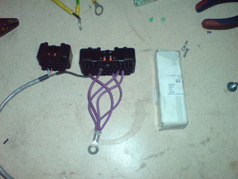
Connectors
4 IRF640N inj FETs
4 22ohm resistors
2 N408AB 14N40FVL FETs
Not mounted jet.
Mapsensor
Anything else missing ?
Topside www.dropbox.com/s/5lrytxlz9129kc4/2013-05-23%2000.39.58.jpg
Bottom www.dropbox.com/s/97iwhmmsr837lg8/2013-05-23%2000.40.18.jpg
27/06/2013
I have connection problems
Any tricks to connect a very old board (number 57) to vemstune ?
im receiving 192byte's from ECU (sending 84byte) before getting "Could not find ECU"
28/06/2013
Problem with comunication fixed, forced into bootloader mode and updated firmware to "1.1.94 bootloader update"
Whats the recommended firmware version ??
Trigger Setup
Is this set up for primary hall sensor ?
Picture: www.dropbox.com/s/5lrytxlz9129kc4/2013-05-23%2000.39.58.jpg
Not really, you need for primtrig HALL: SJ2 closed !!!, SJ6 open (which is so), see GenBoard/Manual/InputTriggerHardWare
Links:
- GenBoard/Manual/InputTriggerHardWare
- [v3.1 schematic]
14/4/2014
Trigger Setup
I found out that I have a VR sensor instead of a Hall sensor... dooh ;-)
R30 = Removede again
C88 = Not mounted
R55 = 10Kohm
SJ1 = Shorted
SJ2 = 10Kohm <- is this ok ?
SJ6 = Shorted
D14 = Not mounted
R56 = mounted again = 10Kohm
C30 = ok
R57 = 75Kohm
R87 = 1000Kohm
C38 = ok
R88 = 10Kohm
C31 = ok
C39 = ok
Mesurement between Trigger1 connecter and LM1815 pin3 = 20Kohm = ok
Mesurement between LM1815 pin12 and AVR pin 29 = 0ohm = ok
19/04/2014
Grounding on fiberglass buggy
Where should i put my grounds ?
Engine is under the black cross
Battery is under the blue cross
Ecu is mounted on a 2mm stainless steel plate, i have prepared a line of 6mm bolts for grounding on the plate.
Where to put GND5. (powerground) ?
Where to put sensor GND. ?
Picture -> www.dropbox.com/s/47uucgpqvje1tc4/buggy-vems-grunding.jpg
- Should I just do like this and connect a big 16mm2 from engine->ecu plate->battery ?
- Sounds reasonable. Should be good as long as "star (or tree) topology" (no ring or other ground loop) and the wires are sufficiently thick. Voltage spikes are more common with non-conducting chassis (eg the USB-RS232 adapter loses connection with sparks, indicates voltage spikes much earlier than any other component). You might need to use shielded cable for triggers, and for ignition. Shield connected to GND only at one end, of course (preferrably at the main harness GND junction)
- 20/04/2014. Ok i found som 50mm2 cable that i will connect battery -> ecu plate -> engine.
- I will shield cranktrigger (at common ground on ecu plate)
- i will shield wires from ecu to ignition coil (at common ground on ecu plate)
30/04/2014
Bosch MAP sensor gives weird voltage (prolly not connected properly)
[Bosch MAP sensor 0 281 002 316 pdf] (0.2-4bar): normal 4bar Bosch
the problem is that the MAP sensor gives about 4.2 volts when the engine is stopped (101 kPa).
- I had expected about 1.7 volts.... Yes, that expectation is good.
- clearly indicates it's not connected properly. Solution: connect it properly. Replace the sensor it it got damaged by wrong connection.
Vemstune shows about 337kpa which approximately matches the 4.2V input: (4.2 - 0.2) * 400/4.6=347 kPa (would be good after offset tuning).
MAP sensor is coupled direct onto the PCB where the internal normally sit, by a cable. That's OK.
I there anyway to calibrate the map-sensor.
Calibration requires at least 2 points. If you can measure at a different pressures, than calibration might be possible.
It would be nice to measure at
- 30kPa=atm-0.7 bar vacuum
- and 350kPa=atm+2.5 bar boost) also.
Do you suspect it's reverse slope (lower voltage for higher pressure) ? I guess there is no accidental pullup to 5V (at least unlikely: for MAP, there is no pullup resistor provision onboard).
According to datasheet, the sensor is normal analog voltage, NOT frequency output like some Ford sensors.
I have checked the wiring again, and you are right..... ground and Vcc is mixedup
- if i want to wire map sensor to EC18 pin6 i have to make a connection from internal map sensor connector to EC18 pin???
- for assembled ECU, ordered with "offboard MAP", the MAP signal is already wired to EC18/6. Otherwise (eg. original board was with MAP sensor but removed later, or if bare mainboard purchased): need to wire of course.
- experiment with a "protection resistor": 0 .. +5V can be safely applied to any pin through a 1k..10k resistor as a test (and watch "analog inputs raw", MAP, TPS, CLT, MAT, ... in VemsTune).
- With the protection resistor the 0 .. +5V cannot cause any problem if accidentally connected to the wrong pin (eg. an unprotected mcp3208 or a push-pull style stepper output channel)
01/05/2014
I have triple checked map-sensor wiring and it actually not wrong, i nearly burned it trying to swap Vcc and ground ;-)
- map-sensor pin1 -> cable core1 -> PCB pin2 Ground
- map-sensor pin2 -> cable core2 -> PCB MAT-sensor
- map-sensor pin3 -> cable core3 -> PCB pin3 Vcc
- map-sensor pin4 -> cable core4 -> PCB pin1 Vout
Picture internal wiring -> www.dropbox.com/s/6i7bnmnc7n04te7/2014-04-30%2015.02.48.jpg
2014-05-25
Changed the Map-sensor to MPX4250... problem solved
Engine is now running :-) but since missing serialnr: ignition is locked at 10 degrees
Vems 3.1 board no57 firmware 1.2.11
vems forum tread http://195.159.109.134/vemsuk/forum/index.php/topic,2290.0.html
Fixed bootloader in serialnr 57, upgraded to uhex.
Stepper (push-pull) output diode protection
What diodes to use on stepper output ?
VEMS (v3.0 and) 3.1 had onboard provision for 2 SMB diodes per stepper output
- D47-D54 any diode >= 1A should do (eg. SMB SS24, ES2J or SMA or throughole: 1n4007, BY399)
- I have some MO16LV
- L293D : 600mA per channel, but strong flyback diodes inside the DIP IC
- L293 or SN754410NE are rated 1A, but external flyback diodes recommended for inductive loads (not needed for LEDs)
- 2 diodes per stepper output if used a'la "full-bridge" for stepper motor
- or 1 diode for each output if activating some normal "unidir" load, as on the Relay subpage of [Rescuekit]
- higher than 1A / output possible via some addon, like L298 if (really) needed. However, when adding more power-outputs, it makes sense to keep stepper outputs standard, and utilize (with PFETs, NFETs or push-pull) 4 of the 7 internally available signals first (2 from p259, 3 from s259 and 2 from AVR). This is getting common (via flying-loom EC10 through frontplate or endplate) with the many V8 (especially with the quad-Vanos BMW S65 and similar engines)
I think I also need D45 on the 12v_p to supply 12volt ?
and from 3.3 there is no D45.
Now running without D47-D54 and D45 is replaced by a wire. Seems to work
- which stepper chip is installed in the v3 have ?
- what load(s) driven ?
- measured resistance of these loads ?