Table of contents
Injector h[0] problem, SOLVED: it was a compiler bug
- At this point this seems to be a compilation problem with your compiler. Reproduced on several boards.
- Prefer the compiled vems.hex in released firmware from GenBoard/UnderDevelopment/FirmwareChanges or at least release candidate, eg. 1.0.13rc13, it is tested not being impacted by this problem
- if you compile yourself, stress this in the report and include version, the output of gcc -v command: gcc -v 2>&1 >gcc-v
I'm installing a VEMS 3.1 on a turbocharged Mitsubishi Colt (port injection, 4 cylinders). Since I wired injectors from OEM ECU to VEMS, 1 cylinder is not working. The injector setting was sequential; h[0]=01 02 04 08 ..., alternate=3. I turned off one and one injectors in h[0], so determined which cylinder has the problem (01 alias INJA) I tried:
- changing spark plug (same effect)
- changing transformator (same effect)
- measured injector resistance (15 ohm, no PWM)
- wired injector from INJA to INJE (changed 01 to 10 in h[0] as well)
- checked if there is voltage on injector with timing light. Even though there was voltage, there was NOT current (measured with DVM in DC 10A mode)
- also checked if I can control INJA channel from h[0]. Wrote 00 instead of 01 in h[0] and checked if test-light turns off (test passed)
- tried to flood spark plug with gasoline (tapped cylinder's ignition to GND). After 1 minutes, the spark plug was DRY, although my timing light on injector was flashing.
- I thought that injector is over, so for a last test wired out INJA wire from VEMS and tapped to GND and measured current, but only for a moment (test passed 0,8A)
- I tried the step above with running engine, and RPM increased, although cylinder 01 was flood with gasoline, so concluded on injector is working
And the astonishing solution: I put 01 injector one step right in h[0] and the problem solved (h[0]=00 03 04 08). After I tried many combinations. Some of them explained below:\n˙1˙
Notice that row 1 and 2 should have been the same, but only one of them working, in the other case 04 cylinder is not working. The situation is the same in the second two cases as well.
Just now I'm using h[0]= 00 05 00 0A setting and engine is working right. BUT WHY DO I HAVE PROBLEM WITH THE FIRST BIN OF h[0]?
Everyone was thinking (reasonably) that another function is using the injector channel. Marcell checked himself that all channel settings was FF in mcd output.
Problem is under investigation, see bottom of GenBoard/Manual/DigitalOut/Table. Hopefully not a loose pointer or sg. As a test I tried to disable some functions like LCD with mdd01 (also tried mdd0f mddf0 mddff) command, but mdh80 still ligths up test-LED for a very short time.
Firmware used (anyway experiences were the same with the lastest firmware): http://www.vems.hu/files/Gabor/firmware_szekeresg1.zip
Introduction
I installed a GenBoard v3.0 on a Suzuki Swift 1.3 8V.
Now the stock ECU handles only the ignition. A self-built GenBoard/VerThree v3.0 handles injection.
VE Learning experiences
I logged the factory ECU at almost all RPM-MAP area, and experienced, that lambda is 0.5V at low MAP and it is _ALWAYS_ 0.7-0.75V at high MAP (1 wire narrow band lambda sond). After I did some log with AVR in open-loop (my j[] table tuning) and saw that lambda variables between 0V and 0.9V depending on VE value. I did the logs above more times and draw the lesson: I should try to operate my EGO correction in closed loop mode always.
I completed the firmware (not committed, it is only in my firmware):\n
static inline void bangbang_ego(void)
{
	uint8_t target, ego_volt;

	if (engine.kpa250<260) target = config.ego_target; // 0.5V, 1kpa=4, 65kpa=260
	else if (engine.kpa250<320) target = 0x1F; // 0.62V, 80kpa=320
	else target = 0x26; // 0.75V

	ego_volt = ego_voltage();
Maybe you think this is dummy, but it works. There was a better solution a year ago (it was dropped when WideBand was proven; maybe it could come back instead of above hack): get the target voltage from l[] table.
Trigger in detail
I always had problem with cranking. I noticed that usually AVR doesn't get trigger at low RPM < 500 (LCD and logging with megatune confirms this). This installation problem is explained above.
I examined my trigger. I have two trigger wires (purple and green) which come from the distributor. I used ONLY the stock ecu for this measurement.
The results:
- There are no voltage on both wires at stopped engine but runnig ECU (this is a VR sensor anyway, isn't it?)
- Resistance between ground: purple 1k, green 20k
- Alternating Voltage at cranking: purple 0mV, green 40mV
- Alternating Voltage at 1200rpm: purple 8mV, green 800-1000mV
- DC Voltage (independent of rpm): green 660-670mV it seems the Japanese ECM keeps it a diode drop above GND.
Alternating Voltage values measured with a simple DVM in V~ mode are peak2peak values divided by 2.82 (fake-RMS).
The lower-peak voltage must go below 0V. With 665mV DC and 60mV amplitude it obviously will stay above 600mV (not go below 0mV in any way). Obviously not good. Take 8 mins to review InputTrigger/AnalogSide and LM1815 datasheet. You need to use a series capacitor: eg. the 10uF 35V 1210 size cap that has pads onboard (from v3.1) so the signal on LM1815 input goes below 0V.
Unfortunately this board is a v3.0, and it has no pad for this series cap - because normally this is not needed at all (series cap added from v3.1 exactly for such hacks).
Just put the cap in instead of the 5k6 resistor, or cut a trace, or put into the external wiring.
PROBLEM SOLVED. I put a series 1uF cap into the external wiring, and now I have trigger at all rpm. I will change the 5k6 resistor soon to cap, but I have to buy one before.
Good. Could you please write 10..15 lines about ve-learning for newbies? Maybe onto page GenBoard/Manual/Fuel/VeLearning.
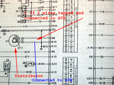
Stealing the trigger signal
The switched ignition signal (B16 on the schematic below), is tapped, and connected to AVR as primary trigger (trigg1).
The service manual, with the wire tapped and connected to AVR:
The circuit that I use to get this into the AVR 3.0
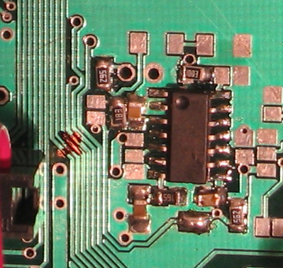
OK, I see this is an early v3.0 with LM1815 soldered by you as the very first SMD soldering in your life :-)
MAPDOT
MAPDOT is working now and has been already in the firmware.
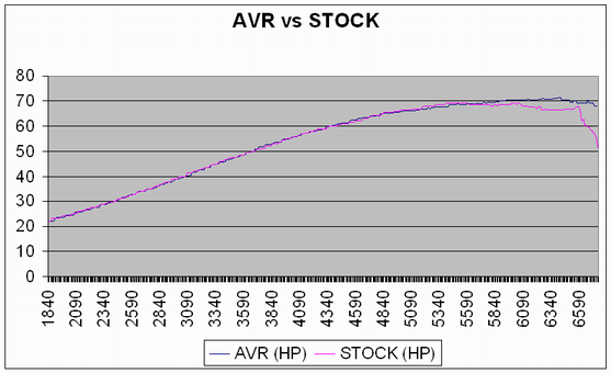
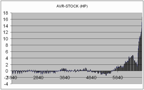
AVR vs stock ECU
I compared the stock ECU with a roughly tuned Genboard 3.0. I did some kickdowns and tuned the VE table at max MAP to be the NBO value about 0.7-0.8 V. So there are some more HP in the engine. I my opinion it will be at least 2-3% stronger above 5000 RPM.
I did the measure with street dyno 0.6.0
My wiring
I have throttle body injection so I used INJ_A (pin7 on Econoseal 36) on AVR. The connected an 5 ohm resistor to the injector channel of stock ECU (check engine don't lights). The wiring of the injector could be simpler but now I can change the injector control from AVR to Stock ECU or v.v. in 30 secs.
Of course the +13.8V RED wire is not directly connected to the battery, it is after the main relay. The injector's common should be after the relay of fuel pump, but if you don't want to wire a lot, you can connect it directly to AVR's 13.8V (RED wire).
Stock sensors on the car:
- unheated NBO2 lambda sensor
- MAP (MPX4115): I simply wired its signal to the avr's MAP sensor signal net
- TS: Only throttle switch. It's signal is 0V at idle, else 12V. I divided it's voltage to avr's TPS signal net. I had to use big resistances, because else the voltage on stock ECU's TPS signal fell and the engine didn't work well.
- note that the 2k49 pullup resistors for CLT and MAT are not populated on the v3 PCB, so the AVR does not interfere with the measurement (pullup R) of the factory ECU
So here is my wiring. It's customized to my car so maybe you have to modify a little bit for yours.
---
Could you upload your config and tables? Would like to take a look at the NBO2 config.. //Emil