Trigger problem page for MembersPage/EricN/Trigger
Problem Description
At any rpm, (tested up to 4000), I loose ignition, fuel pump and fuel injector activity for a very brief split second. Feels like I have shut the board off and on again super fast. Megatune log shows rpm drop to 0 during most of the events but not all seem to get recorded. Megatune shows no resets. With the board out of the truck and on the test bench, fault is the same. For the rest of this page, assume the readings and observations are all off the test bench with nothing but the fuel pump relay and input trigger connected. There are no ign coils, no injectors, no wb02, no idle solenoid, no sensors, nothing is hooked up.
Things I know are not at fault
- Ground- I have 2 gnd wires and 4 gnd5 wires. Only load is the fuel pump relay, NOTHING ELSE is connected. Gnd-gnd5 bridge is cut
- Firmware version- I have tried every firmware version released since 1.0.12, problem has been no different.
- Power supply- Problem happens the same in the truck with 14v, just using a car battery reading 12.4v, or a computer power supply reading 11.6v.
- Input trigger runout- Originally used a [VR sensor] and set the board up for that. No suggestions would help. I have now changed over to Hall type and am using an optical trigger (will detail that later) problem is the same. Used pc signal generator, problem no different.
- Communication cable or Lcd cable failures/faults- problem happens with them connected or not.
- D14- I have tried with d14 soldered on the board (black stripe pointing away from the fets) and disconnected from the board. Also tested d14 to ensure it was still alive.
My best guess
- Config related- I want to wipe the config completely clean and start from scratch. I know how to make (make mtt) and upload a config using the Terminal Program but cant figure out how to make an empty one so I can just enter the variables I need 1 by 1 and test as I go.
- A short somewhere on the board- I measured every pin on the processor while the board was being triggered and looked for change when the event happened and recorded the pins that showed change.Used a graphing multimeter set on 14v, black lead to gnd.
- pin11 2.5v normally, starts spiking a bit to 5v, drops to 0 for a split second when I hear relay click.
- pin23 Looks like a really noisy signal, very rough, didnt record the voltage but it was close to 0v if not at 0v. Didnt reall show any change when event occured.
- pin33 2.39v always, drops to 0v when relay clicks.
- pin47 always 0, spikes at 4.97 or 2.5v when relay clicks.
- pin55 rough line, varies from 1.2-1.6v normally, spikes to 4.5-5v when fuel relay cuts out.
Steps I have taken
Note, I have listed the setup I used for the VR sensor in case there is something I didnt undo when I changed from the VR setup to the Hall setup, CURRENTLY USING HALL SETUP
Here is [the page where I first documented my steps], just for reference. The pics I have used are ones I found off of here
- I cant get my stupid camera to take a descent pic up close.
- try to find a macro mode, it's often a button with flower to be pressed
- Soldered D14 on the board (Red in bottom diagram, black stripe pointing away from the fets) also ripped them off at 1 point but made no difference.
- Soldered bridge across 2 pads next to D14 (grey colored in pic below)Originally had it with just jumpers on the header pins but was told to solder instead.
- Below Ec36 pins 28 and 29 there are 2 pairs of smd pads (bottom side of board), resister is black in the diagram, is marked 271 and reads 271ohms, cap is brown, dont remember what it was supposed to be, was in a clear package with a row of 8 of them. Soldered them on the board.
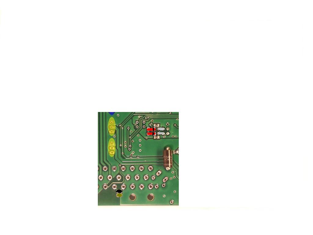
- Removed R30, the resister that is beside the primary trigger jumpers and is parallel to the ec36 connectors (erased off of diagram of top of board.
- Shorted the jumper below lm1815 chip with a peice of wire. (grey in pic of top of board)
That was it for the VR setup. Config was done correctly and confirmed. Problem was evident.
- If it is relevant, I will describe the steps I did to push down the adaptive threshold but I assume it is pointless since I am now using the hall type setup.
Setup for hall, THIS IS CURRENT SETUP
For testing simplicity, I am only using COIL TYPE ign, 6 slots with an optical trigger mounted in a distributer. I know this will not run my cop coils but I will configure it properly if I get this issue sorted out and go to a 12-1 wheel. If I get this problem sorted, I know I can configure everything else properly.
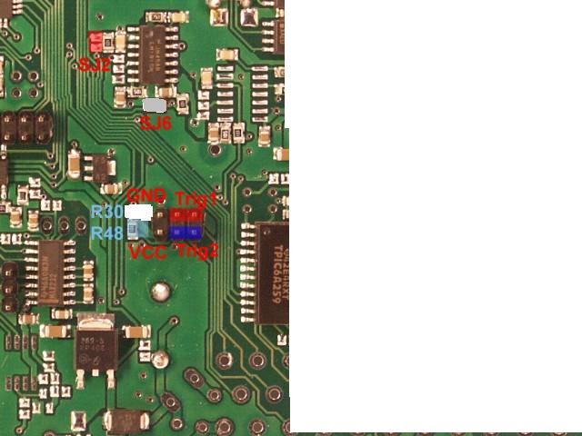
- Cut jumper below lm1815
- Soldered new jumper wire across SJ2 in same place as pic of top of the board.
- Soldered a 2.21k (through hole, easier to do temporarily) resister in place of the one I ripped out (R30, right? correct) beside the input jumper => measure voltage (DC to GND) on both sides of this resistor (with EC36pin27 open=4.85v on the side closest to the trigger jumpers, 5.01 on the opposite side. and shorted to GND =.01v on the side closest to the jumpers and 5.01 on the opposite side) and double check the resistor value (reads 222 or red,red,red,x ?)it is a blue metal film resister, really hard to read the colors but that looks right. Desoldered it and measured, reads 2.2k.
- Measured voltage between SJ2 and gnd, read approx 2.7 Volts I think. 2.7V is a bit low, this might be the problem.see next step Also measure with EC36pin27 connected to GND=.02v (should be max 0.5V, but might be higher with older firmware that had AVR pullup resistor enabled on this pin).
- Removed R56 (right next to SJ2)now reads 4.11V from SJ2 to GND (with nothing connected to the sensor wire), 0.02V with sensor wire shorted to gnd => sounds perfect.
- Can you check the contact at atmega pin29 (IC1) with SJ2 (should be 0 Ohm, or 0 mV in diode mode)zero in both modes. Also check visually (or reheat that pin if you have a suitable solderer. Some tiny amount of flux paste or liquid helps a lot to avoid solder-brigde)definately do not have the hands to do that solder job, used the multimeter test lead on the atmega pin 29 then conected the other end of the test lead to sj2 while triggering ecu, made no difference
- trigger filter is enabled (preferrably, primary_trigger=FE) changed, no better
- the trigger signal is shielded yes
- the HALL sensor has a "decoupling capacitor" (min 100nF .. 220nF) near the sensor, between GND and +5V ?
- did that on the optical trigger and ran it, no change
- not needed on the pc signal generater though
- Connect pc signal generator to input trigger, reads the correct rpm, still cuts out.
Now the input signal and hardware has been verified to a reasonable degree.
The software part:
- firmware version
- Typed Man then mdv result Thu Jan 12 17:24:34 CET 2006
- Typed mdV result 1.0.30
- consider upgrade to 1.0.38
- config (make sure it's dumped from the ECM, same firmware that you issue the mdv, mdV commands to get version! Not your config.txt that you intended to upload, because a wrong global.h version or other error can trick you )how do I confirm that global.h is right, where do I look?
- mcd =\n
primep=64
primep_temp_scaling=80
cwl=C8
cwh=46
cranking_thres=03
awev=28
awev_temp_scaling=98
awc=FF
warmup_clt_range[0]=00
warmup_clt_range[1]=14
warmup_clt_range[2]=28
warmup_clt_range[3]=3C
warmup_clt_range[4]=50
warmup_clt_range[5]=64
warmup_clt_range[6]=78
warmup_clt_range[7]=8C
warmup_clt_range[8]=AA
warmup_clt_range[9]=C6
warmup_clt[0]=AF
warmup_clt[1]=AA
warmup_clt[2]=A5
warmup_clt[3]=A0
warmup_clt[4]=9C
warmup_clt[5]=8C
warmup_clt[6]=84
warmup_clt[7]=78
warmup_clt[8]=6F
warmup_clt[9]=64
warmup_rpm_scale=FF
req_fuel=46
divider=01
alternate=11
injopen=00
battfac=10
kpafac=34
kpaoffs=73
injocfuel=28
injrampup_battfac=FF
injpwm=FF
injpwmt=FF
injpwm6=00
rpmk[0]=07
rpmk[1]=D0
tpsdot_kpadot_conf=00
tpsdotrate[0]=05
tpsdotrate[1]=0E
tpsdotrate[2]=20
tpsdotrate[3]=40
tpsaq[0]=08
tpsaq[1]=12
tpsaq[2]=17
tpsaq[3]=1B
tps_thresh=04
tpsasync=05
acmult=85
tpsacold=20
tpsdq=64
decel_fuelcut_thres=3C
overrun_fuelcut=3C
overrun_fuelresume=32
rev_limit=37
airden_ignore=62
config11=59
config12=30
config13=0A
batt_cal=A4
fastidle=C6
baro=66
dbaro=0A
tps_low=33
tps_high=FF
fan_temp=F1
fan_hyst=05
fan_channel=0F
iac_step_seq=D8
iac_conf=72
iac_max_steps=46
iac_tps_thres=10
iac_cold_idle_temp=CA
iac_warm_idle_temp=D0
iac_cold_rpm=5F
iac_warm_rpm=46
iac_cold_start_pos=40
iac_warm_start_pos=0A
iac_afterstart_rpm=05
iac_afterstart_duration=1E
iac_speed=0A
iac_kp=0A
iac_ki=14
iac_kd=2E
iac_integral_speed=36
iac_integral_limit_dec=40
iac_integral_limit_inc=70
iac_integral_deadband=0A
iac_deadband=05
iac_pid_conf=00
iac_overclose_interval=18
iac_ref_pos[0]=30
iac_ref_pos[1]=30
iac_ref_pos[2]=30
iac_ref_pos[3]=2F
iac_ref_pos[4]=2B
iac_ref_pos[5]=26
iac_ref_pos[6]=20
iac_ref_pos[7]=1B
iac_ref_pos[8]=11
iac_ref_pos[9]=00
iac_sol_channel=FF
iac_ign_advance_change=04
iac_ign_retard_change=04
iac_ign_advance_limit=20
iac_ign_retard_limit=20
iac_ign_threshold=28
ego_conf=06
ego_lag=01
ego_coolant=00
ego_maxtps=FF
ego_maxmap=FF
ego_minrpm=05
ego_maxrpm=3C
ego_warmup=01
ego_lean_limit=40
ego_rich_limit=05
ego_pid_kp=25
mt_unused=00
ego_delta=01
ego_target=19
ego_pid_window=FF
wbo2_warmup_ramp=FF
wbo2_warmup_target=FF
wbo2_abs_limit=F0
wbo2_limit_maxt=FF
wbo2_fallback=80
wbo2_retry_t=06
wbo2_edgetime_corr=BA
wbo2_edgetime_min=50
wbo2_ri_target=96
wbo2_nernstdc_target=99
wbo2_pump_pw_zero=65
wbo2_calibration=BB
wbo2_heater_pid_kp=45
wbo2_heater_pid_ki=11
wbo2_heater_pid_kd=1A
wbo2_heater_pid_ilimit=81
wbo2_pump_pid_kp=15
wbo2_pump_pid_ki=4E
wbo2_pump_pid_kd=00
wbo2_pump_pid_ilimit=FF
wbo2_ri_confidence_scale=80
knock_conf=01
knock_sampling_window=E2
knock1_frequency=29
knock1_gain=14
knock1_integrator=11
knock2_frequency=00
knock2_gain=00
knock2_integrator=00
knock_threshold=50
knock_noise_scale=10
knock_max_retard=30
knock_default_retard=10
knock_retard_step=04
knock_retard_delay=10
knock_advance_step=02
knock_advance_delay=10
knock_minrpm=05
knock_maxrpm=FF
ve_learn_coolant=BD
ve_learn_max_power=FF
ve_learn_rpm_scale=1E
ve_learn_kpa_scale=1E
ve_learn_ego_scale=43
ve_learn_min_weight=4D
ve_learn_speed=FF
ve_learn_limit=FF
ve_learn_conf=01
lcd_c0=07
lcd_delay=FF
lcd_backlight=70
lcd_offs[0]=FF
lcd_offs[1]=FF
lcd_offs[2]=FF
lcd_offs[3]=FF
lcd_default_view=01
primary_trigger=FE
secondary_trigger=02
tooth_wheel=06
trigger_tooth=01
another_trigger_tooth=02
crank_minper=FA
tooth_wheel_twidth1=1E
tooth_wheel_twidth2=00
cam_sync_r_edge_phase=8D
cam_sync_f_edge_phase=21
reset_engphase_after=FE
ign_tdcdelay=6A
ign_dwell14=2F
ign_dwell6=B9
ign_crank_advance=14
ign_out=70
ignchmax=00
engine_off_delay=00
pump_on_mintime=08
fuelpump_channel=40
inj_stage2_rate=00
inj_stage2_start_tps=00
inj_stage2_start_map=00
als_deact_rpm=00
als_deact_time=00
als_deact_egt=00
als_retard=00
als_rev_limit=00
misc1out_minrpm=00
misc1out_maxrpm=00
misc1out_mintps=00
misc1out_maxtps=00
misc1out_minmap=00
misc1out_maxmap=00
misc1out_channel=FF
misc2out_minrpm=00
misc2out_maxrpm=00
misc2out_mintps=00
misc2out_maxtps=00
misc2out_minmap=00
misc2out_maxmap=00
misc2out_channel=FF
act_wot_rpm=FF
act_wot_channel=FF
act_rpm_rpm=FF
act_rpm_channel=FF
egt1_cal=FF
egt1_offs=FF
boost_conf=00
boost_targetoffs=00
boost_minpressure=00
boost_pid_kp=00
boost_pid_ki=00
boost_pid_kd=00
boost_pid_ilimit=00
boost_channel=FF
water_pump_temp=00
hybrid_rpm_a=00
hybrid_rpm_m=00
water_pump_hyst=0F
water_pump_channel=FF
toothrel_normal=79
toothrel_missing=00
fuelcut_min_kpa=00
fuelcut_max_kpa=FF
tach_channel=6F
tach_divider=7F
shiftcut_conf=00
shiftcut_channel=00
shiftcut_time=00
- mct =\n
j[0]=3F80 4980 4D80 4E80 4F80 4F80 4F80 4F80 5080 5680 5C80 6380
j[1]=4180 4980 5080 5680 5980 5A80 5A80 5C80 6580 6D80 6D80 6C80
j[2]=4580 4D80 5080 5A80 5880 5980 5C80 6380 7180 7C80 7D80 7580
j[3]=5180 6980 7780 7E80 8480 9280 9F80 AA80 AE80 AB80 A580 9F80
j[4]=5A80 7C80 8780 8C80 8E80 9B80 A680 B180 C180 BE80 B980 B180
j[5]=6080 8680 8C80 9680 9980 A980 B680 BD80 C480 C680 C080 BA80
j[6]=6080 8680 8C80 9680 9980 A980 B680 BD80 C480 C680 C080 BA80
j[7]=6080 8680 8C80 9680 9980 A980 B680 BD80 C480 C680 C080 BA80
j[8]=6080 8680 8C80 9680 9980 A980 B680 BD80 C480 C680 C080 BA80
j[9]=6080 8680 8C80 9680 9980 A980 B680 BD80 C480 C680 C080 BA80
j[A]=6080 8680 8C80 9680 9980 A980 B680 BD80 C480 C680 C080 BA80
j[B]=6080 8680 8C80 9680 9980 A980 B680 BD80 C480 C680 C080 BA80
l[0]=3F 37 37 37 37 37 37 37 37 37 37 37
l[1]=39 36 36 36 36 36 36 36 36 36 36 36
l[2]=3B 3B 3B 3B 3B 3B 3B 3B 3B 3B 3B 3B
l[3]=47 47 47 47 47 47 47 47 47 47 47 47
l[4]=4D 4D 4D 4D 4F 4F 4F 4F 4F 4F 4F 4F
l[5]=55 55 55 55 5A 5A 5A 5A 5A 5A 5A 5A
l[6]=66 66 66 66 66 66 66 66 66 66 66 66
l[7]=6B 6B 6B 6B 6B 6B 6B 6B 6B 6B 6B 6B
l[8]=6B 6B 6B 6B 6B 6B 6B 6B 6B 6B 6B 6B
l[9]=6B 6B 6B 6B 6B 6B 6B 6B 6B 6B 6B 6B
l[A]=6B 6B 6B 6B 6B 6B 6B 6B 6B 6B 6B 6B
l[B]=6B 6B 6B 6B 6B 6B 6B 6B 6B 6B 6B 6B
n[0]=26 32 37 39 3F 41 45 47 50 4E 4C 4A
n[1]=28 31 3B 3F 44 48 4E 4E 56 54 50 4E
n[2]=2A 3E 44 47 4C 51 55 5C 5A 56 54 50
n[3]=2C 42 49 53 5B 5F 64 62 5E 5C 58 56
n[4]=2E 44 52 5C 66 6A 68 66 62 5E 5C 58
n[5]=30 48 56 62 6C 70 6E 6A 68 64 60 5E
n[6]=32 4A 5A 64 6E 72 72 6E 6A 66 64 60
n[7]=32 4C 5C 68 72 76 74 70 6E 6A 66 62
n[8]=36 50 60 6C 78 7C 7A 76 72 6E 6C 68
n[9]=36 52 62 70 79 7D 7D 7A 76 72 6E 6A
n[A]=38 56 68 74 7A 7D 7F 7D 7C 78 74 70
n[B]=3A 58 6A 78 7C 7E 80 7E 7E 7A 76 72
k[0]=14 1E 32 46 5A 66 78 8C A0 B4 C8 FA
r[0]=06 0B 0F 13 18 1C 21 25 29 2E 32 37
h[0]=20 40 04 08 10 20 40 80
h[1]=00 00 00 00 00 00 00 00
h[2]=03 01 05 02 04 00 00 00
b[0]=28 30 38 40 48 50 58 60 FF FF FF FF
t[0]=20 40 17 80 A0 C0 E0 FF
- mcd =\n
If we find nothing, you'll need to try another genboard so HW / SW side can be told 100%. Please fire a WebShop order (choose IBAN, no need to pay) for a non-assembled genboard (will be sent from USA) for experiments.