Board setup for MembersPage/EricN/BuildNotes
- Soldered connector to board.
- Make [Serial Cable] and connect it to your PC and Connect the other end to your board.
- Power the board. Out of fear, holding everything in my hand to feel if anything getting hot
- at (with 1A fuse) EC36 pin 25 (+8..14V)
- and (-) EC36 pin26, EC36pin5 (EC36pin21, EC36pin32). Be certain to connect at least one GND5 too. While this is not strictly necessary if no load is driven from the power-GND5 plane, we better condition everyone to always have as many GND5 connected as possible (3..4 in a production install)
- Download and open Bray terminal. Use [this link] and follow his instructions. If it works, good, if not, make sure you used a capital M in Man and com port is correct as well as your cable is built correctly.
- Download the [firmware] make sure it is the latest release.
- Downloaded and installed [winavr] so you can have programmers notepad, only need it to enable wb 02 in my make, (I dont know of another way)
- To enable wbo2, read [this page] of the manual. I opened programmers notepad, opened folder firmware/doc and opened the my_make file there. Find the part that says MY_CONF += -D WBO2 and erase the number symbol. Copy my_make into the the firmware folder and save. If you are using a different sensor other than gm compatible type ones, I think now is the time you have to use the [EasyTherm page] Didnt do it, not sure how, figure it out when/if I need to do it.
- MembersPage/JohanEriksson/VerThreeFirmForDummies will get your firmware uploaded.
- Uploaded firmware using avr studio 4, took a bit of playing to figure out what I was doing, need to try it again while I remember and document the steps for next time.
- Downloaded and installed [MegaTune] run it with the board connected, seems to communicate. I didnt do any special steps in relation to the firmware, as far as I can tell, the latest firmware release is already setup properly for megatune. I just unzipped it (cant remember if I had to click install or not) and it worked. resist the urge to change anything yet, may screw up mdh testing later, see below
- Connect MAP CLT TPS AIR TEMP sensors, refer to [this page]for pinouts and wiring diagrams. Remember, the sensors ground to EC 36 pin 26 but run the wires as far from the ecu as possible, right at the connection point of the ground. The other grounds (EC36 pins 5, 21, 32) I assume are for the ecu to use for grounding stuff like injectors and relays etc. I conncected the map sensor with wires as mine is external. In the pic below, the map sensor holes are right above the VEMS logo. (note the pic is of the bottom of the board) The wire on the far right is the signal, next is ground and the 3rd is Voltage (the rest are just for mounting the sensor I assume). I just ran the 3 wires to my honda connector and out to the map sensor.
- Power up your board with the serial cable connected, open megatune (make sure no other serial programs connected or you wont connect) guages in megatune should read the sensor. IAT and CLT should read the same (should be room temperature if they are already GM compatible ones). Hold them in your hand, make sure the readings get warmer. Sweep the TPS, see if it works and suck on the map sensor, should show change.
- Soldering stuff on, start with the FETs, easy to do and good to warm up on before tackling the surface mounted stuff (which, after you figure it out, is easy enough). FETS can go on top or bottom, just as long as they have something aluminum to clamp to for cooling. I think maybe the Alubus case would require it to run on the bottom or you would have to modify stuff. BUT I am making my own case to match my Honda ecu connector so I put mine on the top. Plus I am trying to make the case as skinny as possible so it will squeeze into the slot I have for it. Top or bottom, if looking at the side with the writing, I called the pin on my left pin1. I made sure that my pin 1 is closest to the EC 36 connectors.
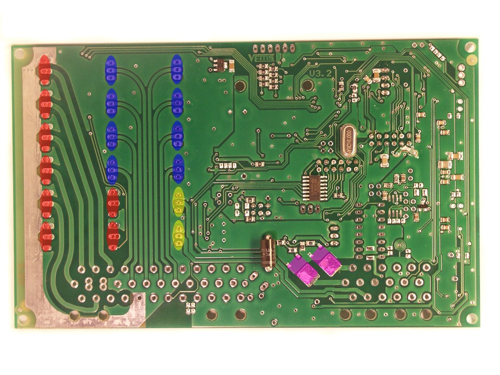 This picture shows orienatation of all the fets including the dpak (purple) as viewed on the bottom of the board. Yellow is wbo2 with channel 1 being closest to the EC 36, blue is injectors, red ignition IGBT's. When mounting the IGBT's to the aluminum heat sink, they have to be electrically insulated from the aluminum or something bad will happen.
- If I actually remembered to order the dpak fets, they would have been soldered on now. (remember I didn't get them because there were enough outputs availabe for what I need) make sure you use a flyback diode if driving inductive loads with the DPAK FET. The flyback diode (eg. BY399 is fast 3A, or 1n4007 is slower 1A diode. ES2J is a fast 2A SMB footprint SMD diode) can live in the harness, or on-board (no dedicated pads!). The lack of flyback diode will ruin the DPAK FET and possibly cause other damage when inductive loads are driven.
- I guess [flyback] would be next, mine were alredy on. Remember too that you need to send a wire from the EC36 Pin23 with the flying wire on it to the wire that supplies power to your coils and injectors, BUT it must connect on the opposite side of the fuse that the components are on so if the fuse blows, the flyback is still connected to power.
- Because I am using LS1 smart coils, I omitted IGBT's and placed a jumper wire in its place between each of the first 2 holes closest to EC36, connecting the AVR pins right to the coil trigger. If it works, I should add it to the IgnitionPage. Some readings I have from a vehicle running these coils can be found on my MembersPage/EricN .
- Not sure if this next one is important, it seemed to be pretty obscure to find but if using a Hall sensor, below Ec36 pins 28 and 29 there are 2 pairs of smd pads (visible at the very bottom of the board in the above pic). The one closest to the connecter got a resister with 271 written on it and the one below it got a capaciter from rescue 2 that was in a clear package with a row of 8 of them. ec 36 PIN 28 is power for the HALL sensor.
- [Stepper motor hardware] installed. The 10uF (1210 size, 35V) capacitor is soldered on the bottom of the board: on the 2 SMD pads between the 4 legs of the stepper chip that are almost touching the EC18 pins 4,5 and 6.
- The D45 : find the throughole pad down south, at the boardedge (almost middle). You can verify with DVM that this connects to SN754410 stepper chip pin8. Feed 14V into this with a short wire (from the closest pad or the fuse or inductor) and there you go. Thanks, I guessed that had to be it, wasnt sure, was expecting SMT pads.
- Next I soldered in [d14] for input trigger. They really suck, dont know what they do exactly but it is crowded, hope they were important. Double checked with DVM in diode mode to make sure there were no shorts and I didnt melt the things with all the time I spent chasing them around the board with tweezers and soldering iron.
- Set up the [input triggers]. That page of the manual is awsome in its clarity. The only thing it is missing is optical trigger, which I assume uses the same setup as Hall.
- Now built the rest of harness, need to find Corel Draw to use the fancy drawings like everyone else. Followed the [pinout] from someone else. Remember, the sensors all ground with Ec 36 pin 26.
- Started playing with mdh commands, Ign channels all work well
- Got serious, maybe not important but tested all the mdh channels. It was good as it helped me understand stuff alot more. Refering to [digital out assignments] to reference which command activates which channel. The first column (ie specfet, I259 etc) refers to what "chip" is doing the job. You will also see it in MegaTune . SPECFET I think are the dpak fets, for the rest, it is just as easy to read the comments column on the far right.
- Open the terminal program and type Man for manual mode (case sensitive).
- Now, lets start with the first one I did (and screwed up when playing in MegaTune first). The fuel pump relay. In the end, you can use any channel you want, it is just nice to follow some sort of standard when you are struggling. Refering to [the table] if you follow the row that says fuel pump relay in the comments, you will see it is on EC36 Pin15. I connected a relay to EC36 Pin15 and the other end to power (remember, with the stepper chip being the exception, ALL that the ecu controls is ground). If I remember right, all the circuits that are on P259 do not require flyback when running a normal relay etc. as it is built into the chip.
- Now, follow the row again and you will see D7/57 under the ON/OFF column, pretty self explanatory. Now in the terminal program (or on the keyboard), with lower case letters, type mdhd7 and the relay clicks on. Type mdh57 and it will turn off. Did this for all of the P259 channels.
- For the injectors, they need to be defined (later) if you have any hope of activating the one you intend to. Injector related mdh commands, like mdh50 and mdhd0 switch the channelS defined in h[0], element 5 for mdh50 and mdhd0 (that is a mask for 0..8 channels, usually 1). (will explain that when I fully grasp it as I roughly understand it now, but havent done it yet)
![[d14]](http://vems.hu/www.vems.co.uk/VEMSWB/D14Placement.jpg)