This page is about aspects of mounting the circuit, in either of the two available case options. The Alubos1600 case is the most cost effective for which the design was optimized while the CnC case is significantly smaller and easier to work with. The concerted effort - as always in VEMS land - cut custom fabrication pain and individual parthunting to minimum, saving time for the fun part.
If you like, you might find Alubos1600 100mm box close to you, check
- [Bopla's webpage]
- or order it from WebShop - this way you can choose between 0/4/6 holes drilled to our standards for 0/2/3 clamping plates.
- The CnC case will be available shortly via the webshop as soon as they are in stock.
Jörgen made some endplates, here's is a cased VEMS GenBoard 3.0 with EconoSealIII:

Check out how the switches are clamped to the case:
(note: there are 2 types of alubos drill, the picture shows the more frequent type for which the TO220 legs are bent in 110 degree; not 70 degree, as for the rare one; bent to 90 degrees on the picture, not ideal.)
Check out the newer, better frontplate design at CaseFrontplate.
Please help us design a new awesome GenBoard/VerThree/CustomCNCCase
The old ones:
![[endplate1 closeup]](http://www.squirrelpf.com/msavr/files/endplate1.JPG)
![[endplate2 closeup]](http://www.squirrelpf.com/msavr/files/endplate2.JPG)
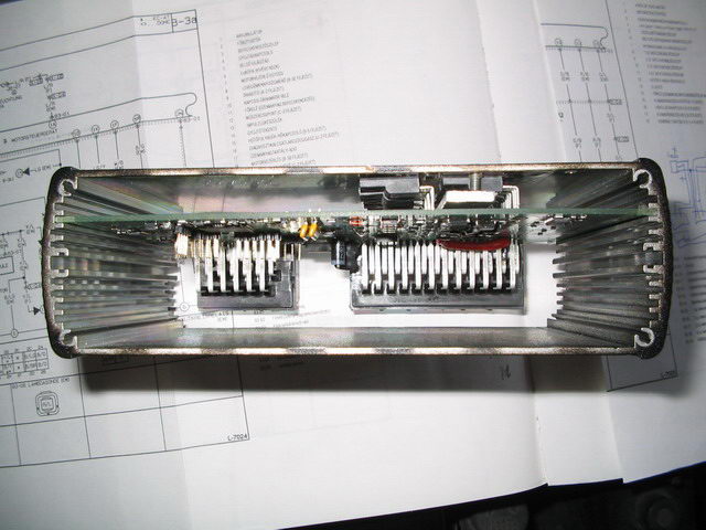
FETs to the case/heatsink
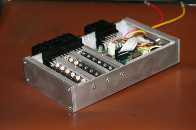
[picture about the favorite mounting, 2 lines out of 3]
![[picture about the favorite mounting, 2 lines out of 3]](http://www.american.hu/GenBoardv31/GenBoardv31_assembled/Genboardv31_assembled_0010.jpg)
notes:
- there are other options, but make sure you don't swap the gate and the drain of the switches.
- main idea is to clamp max 6 switches (FET/IGBT) with a single (eg. 3mm thick Al) plate, secured with 2 screws. This is fast, and works very well.
- the special plates on the picture with 6 screws and 6 holes are not part of the mounting, they are tools used to align the FETs nicely when soldering.
- the 2 holes (with thread) are not at the centerline of the clamping plate, but divides the 3x15mm Al as 15=6.5+8.5mm.
- The middle plate is reversed, therefore the holes are not equidistant (but 20 + 25 mm apart, see this [picture about the necessary holes for the clamping plate screws] on the top of the Alubos
- FETs from WebShop are insulated by their own coating (but added SIL-PAD insulation does not hurt)
- IGBTs must be insulated from heatsink! This is very important
- Fitting the clamping plate and screws after the genboard is slided into the Alubos is not too hard when the clamping Al plate holes have thread in it (and they do).
![[picture about the necessary holes for the clamping plate screws]](http://www.vems.hu/files/genboardv3/CaseAndMounting/AlubosClampingHoles.jpg)
Electrical insulator that conducts heat
For usage under the IGBT. WebShop lists it as insulatorsheet ("output drivers" category).
PCB in the Alubos
There would be several slots to slide in the PCB, but we decided to put into the 2nd slot:
10.2 + 1.8 + 22 + 1.8 + 10.2 = 46 mm division sounds right (designing for the worst case, when 2 boards are in the case, both having EC36 connector - on different endplates of course).
Is the 22 mm between PCBs enough? Yes, the EC36 will clear, if the PCB is 98mm, not 100mm. If it was 25 mm or more between PCBs, 100mm could be used. No problem.
The 10.2 mm below PCB is perfect for mounting the FETs with clamping plate and insulator.
0.3+4.5+0.3+3=8.1mm, smaller than 10.2mm, good. Not having through hole or any SMD on the blue side is nice.
See CaseFrontplate
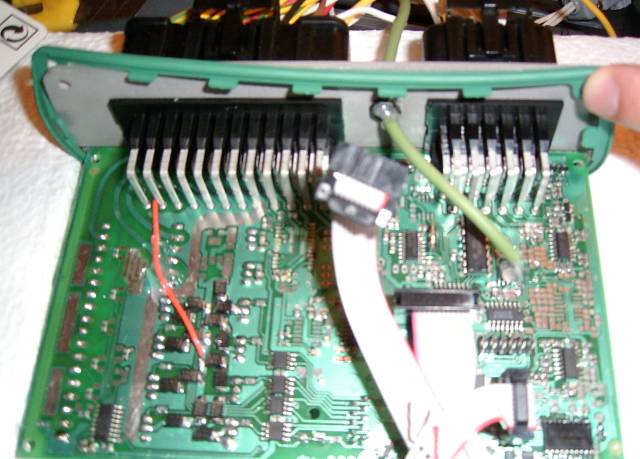
An early v3.1 board with flying loom K-compensational (for ExhaustGasTemp) cable. Usually the LCD and PS2 is made with flying loom (and a 3d frontplate hole hosts pneumatic MAP connection), sometimes LCD and EGT. In this case only an EGT is made flying loom style, because DSUB-capable endplate is used for LCD and RS232 (and PS2 is flying-loom through endplate).
Connection for non-mission critical signals
Signals for LCD, PS2 and some other subsystems are not essential for the engine to run, but they are still nice to have. There are some installer options to get them out of the assembled GenBoard/VerThree:
- [endplate mounted DB25] Note that only endplate with DB25 and DB9 is available now (2 windows). Convenient to have independent connection for - say - RS232. (The endplate with DB9 and DB25 windows is missing the two cutouts for the gasket. At least the one I got. No big problem but maybe it should be there. /Johan Rius)
- DSUB15 fits on the frontplate, vertically between the EC18 and EC36 (but 0 such frontplates have been manufactured, and filing takes some time)
- 6.3 mm Jack is sometimes used for serial port. A 6.3mm male => 3.5mm female adapter plug can be kept in while the notebook is not connected (to protect from liquids).
- simple round cable(s) through the frontplate with gromet. Wire-wire connector (DSUBxx, MateNlock, trimtrio or molex) can be used to disconnect the ECM from the LCD mounted in the car. This is very common for PS2 where "PS2 Extension cable" (WebShop) can be used easily (starts with cutting down the minidin6 connector from the male end). Eg. a cable for PS2 and a 12 wires + shield cable can be used for LCD + RS232. Remember that shield must be grounded on the ECM side only. One of the core wires must be used for the GND signal.
![[endplate mounted DB25]](http://www.vems.hu/files/Fero/wiring/013.jpg)
[image of frontplate with MAP signal connection, and holes for LCD and PS2 keyboard]
![[image of frontplate with MAP signal connection, and holes for LCD and PS2 keyboard]](http://www.vems.hu/files/genboardv3/CaseAndMounting/GenBoard_v3.x_front_with_extras_m.jpg)
Misc
- v3.x PCB measures 160x100mm (actually, 160x98 mm but that dimension does not matter)
- [some pictures] that should be cleaned (at least resized) and linked from wiki (or some items from shop)
Mounting alubus case in the car
- Most common place is the passenger side, at the foot
- an L shaped Al (eg. 50x50mm) mounting flange can be used instead of the endplate. 4 drills for the Alubos, and 4 drills for mounting
- the simplest method is just a few wraps of tape, or thin plastic belt around the alubos, eg. between the EC18 and EC36
- some 'rubbery thing between the Alubos (or mounting flange) and the chassis is highly recommended in any case. Otherwise it will make noise and both parties will be scratched.
TODO: pictures of mountings
cnc Case
This case is cut from some scrap extrusion. It is in 7 pieces (3 heat sinks the case, top and 2 end caps. There are a couple of options available for the end caps. They include a weatherproof AMP circular plug, DB15 and DB25 as well as a blank. Although currently available in natural aluminum the case may be available anodized in the future.
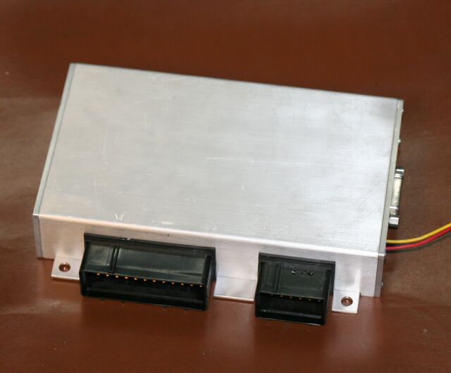
Completed ECU. As you can see the bottom plate forms the mounting tabs. This may possibly change before production to use some 90 degree extrusion for the endplates. The reasoning behind this is that the EC clips can be difficult to reach if it is flush-mounted.
Considerable effort went into designing the heatsink system. It was designed to be thermally efficient (clamping to the cover) as well as allowing the entire board to be removed from the case in a reasonably efficient manner. I've used nylon screws for the IGBTs with standard heatsink insulators to isolate them from the aluminum heat sink.
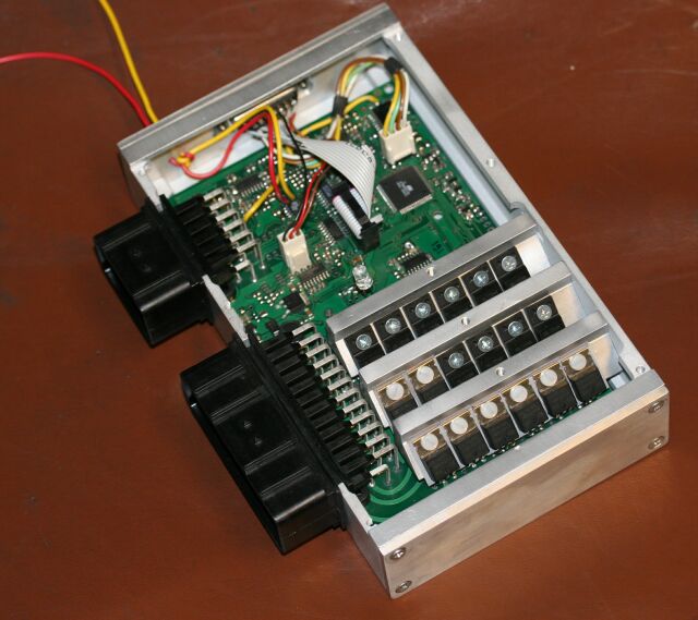
The 3 heatsink pieces are already drilled and tapped. The fets and IGBTs can be mounted and then soldered to the board according to the installer's preference.
The completed board is then dropped into the case with the heat sinks attached. 3 orientation screws clamp the heat sinks to the side and once the top is added there are 3 additional screws that clamp them to the top of the case for thermal transfer. If a weatherproof installation is required you can simply coat the edges of the EC connectors with RTV as well as the top and endplates.
This is another view of the heatsink mounting. For orientation in this example the fets and IGBTs were soldered in using about 1mm of protrusion on the leads without trimming them. With the slight bend there is enough play to make up for slight differences.
Look forward to this option being offered in webshop.