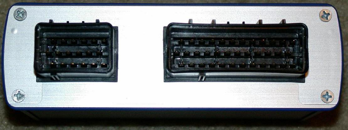
Alubos front-plate with window for econoseal connectors
Al and transparent frontplates (and endplates) available. The frontplate is split, and features machined slot for the EC36pcb and EC18pcb connectors. The endplate is closed (with just the 4 screw-holes at the corner) or features DSUB25 and DSUB9 windows for custom signals (possibly LCD).
[ http://www.american.hu/GenBoardv31/GenBoardv31/TransparentBox/ unresized big pictures about box with transparent frontplate ].
They use a precise, but expensive technology for transparent plates (used for demo and production purposes).
Assembly warning
It is very important to solder the EconoSealIII connectors with the frontplate applied and verified to the GenBoard/VerThree/CaseAndMounting : otherwise it might be impossible (or say hard pain) to apply frontplate later (without unsoldering connectors) depending on how the connectors were soldered.
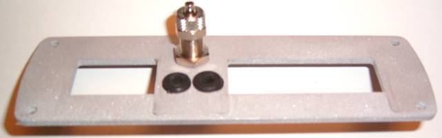
Frontplate with pneumatic connector. The pneumatic connector is for 6x4mm size pneumatic (vacuum-bearing!) tube. The connector codename "VIV" is in WebShop. The 2 other drills (with small rubber rings in them) are usually used for LCD and PS2 flying loom cables, sometimes LCD and EGT (than the PS2 only consumes 2 EC18 pins, since EC36pin26 GND and EC36pin28 HALL-suply can be utilized).
Manufacturing notes
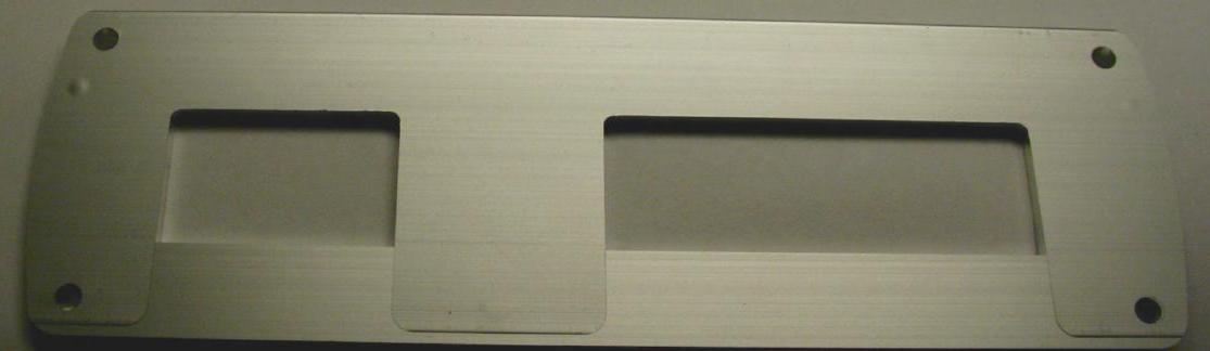
looking onto the side without gasket-notches:
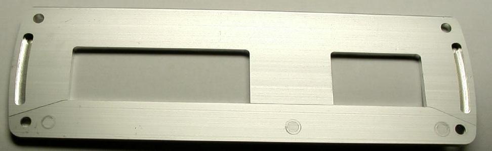
looking onto the side with gasket-notches:
The assembled box:
the part press fit together you need to smash them together with a vice or tap them together.
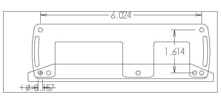
to verify sizes (this picture uses the broken inch unit :-):
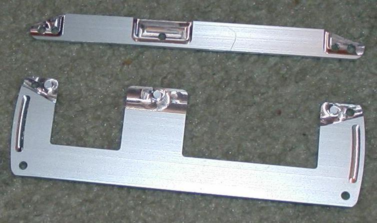
Simple endplate and OLD, OBSOLETE frontplate :

- We also want to manufacture endplate, but that is really simple when the frontplate is designed. it's just one peace, without the windows for the connectors. The gasket-notch is still there on the endplate too, not seen on the picture because it is on the other side.
- We do NOT want to manufacture the old frontplate design, because having the screws in the overlapping section is really nice
TODO:
- simplify the design: machine time should be decreased. See below.
- relocate manufacturing to (near) Budapest, Hungary (we need a reliable still cost efficient partner)
- organized repository of CAD files (maybe in restricted repository)
Simplify design
- we apply a 2 dimensions design: using 2 levels: drillthrough (and boundaries) and overlap section (and the third is the not-machines full 3mm)
- We want to drop the keying. The 2 screws will be just enough. No nead for it to withstand nuclear catastrophes.
- the overlap at the middle section should be small (3..4 mm). I suggest 4 turns, 135 degrees each.
- the overlap at the corner should be small (3..5 mm - the hole must be in the overlap, fully). But remember: no aligning sticks... 135 degree turns preferred here too.
- do we want a VEMS text somewhere ?
- do we want DB15 hole on some endplates ?
No need for these with the 2D machining:
- Radius should go up ++. Such sharp, small radius corners (where the boards meet) should not be needed. This will not be an issue because of the 2D machining
- the bigger radius should also apply to the seal-notch. Ideally the notch should be done with a big tool in one go. There is really no size-tolerance requirement for that notch (no sealing or other purpose, just to clear the aligning lobes of the alubos gasket). The notch will be V shaped with 2D machining.
- currently they are a little tight on the EC connectors (in all directions) and could use another 0.03 .. 0.1 mm clearance (otherwise they are hard to assemble and really hard to remove after installed). Some manual (drill and sandpaper) could work here to decrease width, and the adjust will happen automatically when the boundaries are adjusted for 2D manufacturing. Especially if sanded in the end.
Surface finish - optional
options:
- sanding
- eloxizing (cool colors)
What format is needed to manufacture? - alternatively they can just redesign, given the pictures, files, Alubos and connectors.
- they couldn't use the .MC9 files (are they specific to an environment?)
- mc9 == mastercam version 9
I can export but it take some work on the import it seems that inporting/exporting from one CAD to the next seems to always need some work.
The HU countryside (unreliable partner) shop could use
BUT THIS IS NOT GOOD FOR NOWRequired format: we need this for now:
- Coreldraw or
- EPS encapsulated postsript: with different colors (preferred) or different files for layers.
The 2 part frontplate must be in 2 different files (especially if it is EPS). One better be mirrored so the same sheet-laying and tool-mounting logic applies. The height must be specified as extra input: simple in this case: the mid-height is 1.48 mm (total is 3.00 mm, but 2*1.5 mm will be somewhat > 3.00 when put one onto the other).
Don't worry too much: we will adjust the edges, especially at the overlapping section after the test-run. I think the edge of the overlap section when going from half to full height will be angled so a faster tool can be chosen: so the boundary will have to be offsetted a bit unless the edge refers to the mid-height (which it should, IMHO, so probably no worries).
Measurements in mm
Plexi version's division1 (all referenced from ECxx top edge):
-16, 21 (EC.. window), 36 mm
(just 1 mm lower than on [this pic], which is -15, 21, 37mm. The truth should be somewhere midway: -15.5, 21, 36.5 mm although if it's higher, the EC can be raised without much problem.)
![[this pic]](http://www.vems.hu/files/frontplate.jpg)
division2 (all referenced from left drill):
13.0 (EC18 window), 45.9 , 76.0, (EC36 window) 138.9 , 153 (right drill)
the side is not straight but a parabola: climbs 4 mm on +-24mm:
4 = y = 1 / 144 * x * x = 1 / 144 * 24 * 24
Radius at EC36 and EC18 top: 2mm
Radius at corners: 5..7 mm
The above data is enough to make it's size match. The rest is free to size. Please verify.
Latest frontplate design - 2004.Nov
![[Picture]](http://www.vems.hu/files/frontplate_bigger_overlap_EC_hole_centered.jpg)
![[Picture without dimension lines]](http://www.vems.hu/files/frontplate_bigger_overlap_EC_hole_centered_no_dimensions.jpg)