Normally order VEMS ECU with the correct number of knock inputs and see GenBoard/Manual/KnockSensor and [VT help knock configuration]
If missed to order VEMS ECU with the correct number of knock input - or need some deeper diagnostics, you're on your own, but these can be useful (and the HW is not very complex at all):
How to install if home-modding ?. Take ESD precautions !
- I did buy a motronic55 Audi AAN box but forgot to order knock X 2.
- installed the knock chip and crystal so is there anything else I have to do to get it to work?
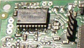
- TPIC8101DW (take care of orientation)
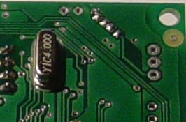
- 4 MHz crystal on the bottom side (with insulator under)
AFAIK that is all, but we test it (and enabling: configuring it is needed).
- Very simple circuit (we usually test with sound audio signal, with 24-1 1 of the channels have different amplitude).
- The squarewave pulses have 6..7 kHz component also.
- Otherwise generated c270 signal around 2900 RPM also makes sense : 2900 / 60 * 135 = 6525 Hz (6700 Hz is not far from knock freq of automotive cyl bore-sizes)
The knock schematic and layout is exactly same on AAN as on
v3.6 or other v3.x, see GenBoard/VerThree/Schematic
The signal path is only a few resistor and capacitor, if the TPIC8101 is there with the 4MHz quartz, not much else to it. See below while following schematic if need more.
Old, but hasn't changed AFAIK
There is also an analog signal output from [TPIC8101] => AVR ADC
- that is NOT needed, NOT used for knock, and never have been used (the firmware reads all knock data via SPI interface, not analog signal, therefore HIP9011 is not good and will not work).
- actually the analog input has been reused as 1-wire I-button keepalive capacitor.
GenBoard/VerThree knockdetection HW
Needed for Knock Sensor input:
- R1, R2 Knock Channel 1 (10..22k) (analog signal amplitude gain can be adjusted with these; but also in the digital domain - in config)
- R3, R4 Knock Channel 2 (same as R1,R2)
- R17 1M
- C1 Knock Channel 1 (100nF)
- C2 Knock Channel 2 (same as C1)
- C14 0.22uF
- C16 100nF
- C18, C19 22pF
- Y2 4MHz XTAL (16MHz might work with matching config)
- U5 TPIC8101DW (not in rescue kit! Optional, see WebShop)
C17 is no longer used. (was: 2.2nF, can now be left off)
V3.2: if you ordered knock-kit (in same order as genboard) than U5=TPIC8101DW and Y2=crystal already soldered onboard (crystal missing on a few boards sent out before 20041030.)
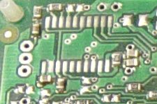
Here you find the top-side components, the second channel uses components on the bottom side too. (thanks to Mr Grogan for pic)
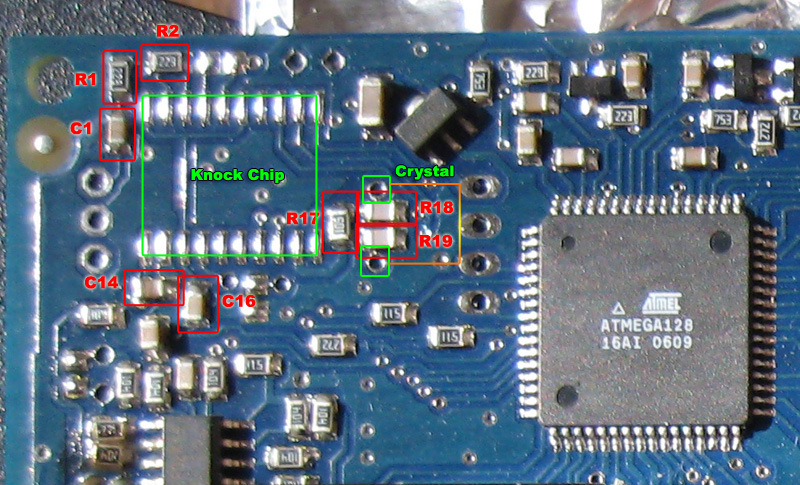
The knock sensor chip installation:
Pin 1 points to the connectors-side. (so pin 1 points to the short side of the board)
The crystal goes next to the chip.
For the 2nd channel, the following components are also needed:
- 100nF (or 220nF, does not matter which) in the diagonal position
- 22k in the diagonal position. As this is in series with the 100nF, they can be swapped: it does NOT matter if the resistor or the cap is closer to the input
- 22k (on top side, next to R2)
v3.3
The knockchip and 4MHz crystal is installed (if ordered v3.3 with knock-kit), the only thing needed is to connect the sensor input through the 3 pin header (pads) at the northwest corner (looking at the "top") :
- North pad (close to board-edge): knockA signal (channel 0) (usually through EC18pin3)
- Middle pad: knock GND (usually through EC18pin2)
- Southern pad: knockB signal (channel 1) - usually not used
TODO: take pictures of board region around knock chip
If the knock signal is not routed via EC18, it can be routed through a connector or flying loom cable mounted through frontplate or endplate.