Changes by last author:
Added:
|
Airfeed related page for MembersPage/MarcellGal/EngineSwap
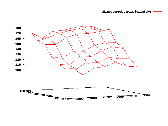
Since the project reverted to an NA setup because of a space conflict between air conditioner and turbo, the (NA) airfeed is very simple. The only trick is the variable intake, actuated by GenBoard. Here is the measured VE (unscaled). Used formula: VE=100000*PW/MAP/req_fuel, where PW is the real pulsewidth from * log taken with MegaTunix * formatted (optionally averaged) with firmware/bin/mtx_loganal.pl * plotted with gnuplot load firmware/bin/mtx_loganal.gpl Since the incredible EGO correction is used with WideBand controller, the pulsewidth were corrected on the fly to match the real airflow.
As you can see, the step from 70..80 kPa is where the variable intake is actuated. Significant from 1000..2000 RPM. This is because I configured GenBoard so the variable intake is only pulled to the low-RPM (longer runner) position above MAP > 80kPa. At 2500..3000 RPM the difference is small, and above 3000 RPM the actuator is off. Note that the above is averaged data, that also includes data from not-yet-actuated intake at the loadsites where actuation is desired. The actual effect is bigger than this, around 15%. The reason is that after reaching the condition for the variable intake actuation * actuator needs some time to actuate mechanically (appr. 300 msec) * EGO correction needs some time to react (100 msec range) * it is also possible that the vacuum container is consumed too early. Evaluating time-domain data (vs. averaged) could reviel this This can be viewed in the dot-plotted 3D view, see firmware/bin/mtx_loganal.gpl for notes. The dot-plotted data is unviewable on a steady 2 dimensional image. Only viewable as you drag it around in gnuplot (to change viewing angle). Consider * adjusting VE values for these loadsites: will eliminate some EGO delay. * changing actuation to 70..75kPa (adding MAPdot would help here) might eliminate some delay that is cause be the mechanical actuation time * changing RPM actuator range to 1300..3000 could help the early consumption of vacuum a bit. There is not much benefit at 1000 RPM anyway ---- When I first started the engine (without air filter box), it had a loud shhh sound like a gas turbine sucking air, so next task was to bolt the factory airbox (air-filter) on. The tube that I could buy fast sucks, not smooth inside, so restricts airflow badly (appr. 10kPa=10% at high power), and a bit loud too. When I replaced with smoother tube, it became nicer. TODO * Take pics * take out some ducttape (and replace with other materials :-) ---- Idle air I have a (4-pin) bipolar stepper with 46 Ohm windings. Connections: * A-B * D-C From [any bipolar driving cheetsheet] I concluded that 0-1 and 2-3 must be driven a half period away from each other. So I need either * 3,1,2,0 (=0xD8) (just checked: this is what mik has) * 3,0,2,1 (=0xC9) (this is what anti-miks have in a world made of anti-material). Actually this was the right direction for my setup, because connection to my 4 stepper pins succeeded like A,B,D,C for historical reasons. I played a bit with mdi.. (force iac position) * mdi0e 780RPM * mdi0f..mdi14 allows the idle controller to maintain 830 RPM with -8..+4 degrees ignition advance (on warm engine). The stepper valve opening is huge. I ended up setting the iac reference positions higher than necessary for the target RPM (at the relavant temp), so iac PID integral is normally negative. At the same time, I set very low iac_integral_limit_dec (=06). This only makes sense with iac_ki value and stepper parameters, so copy the idea, not the actual value. This makes it almost impossible for the engine to overshoot badly in the negative direction (=> stall). When we first started the engine, we accidentally had iac_conf=0x18 (somehow mix-matched this variable from Dave's config instead of mik's) instead of 0x1e so stepper iac was disabled. The iac was approximately halfway, enough for 5000 RPM idle. The idle was regulated by overrun fuelcut=1100 RPM and overrun fuelresume=900 but it was terrible to drive, because * very bad for the drivetrain when hitting overrun fuelcut every second * the WideBand ego correction cannot work when the overrun fuelcut activates (because fuel is cut and it goes lean, obviously). * also I had to add some throttle (not much, since iac_tps_thres was set _very_ low) to make the engine leave overrun fuelcut, but than it was a bit too powerful to start nicely. I'm glad that I found the stupid hiding stepper-enable bit2 finally. iac_conf line in global.h needs some attention (~copypaste from iac.h) ---- Faster startup with throttle=0 The engine starts immediately, but without throttle pressed it takes a bit long, appr. 1.5 sec to reach target RPM. I think that this is caused by the iac stepper goes back to the reference position very fast after leaving cranking mode, and than climbs back again with the integral (than down again after reaching target RPM). TODO: * follow iac position on LCD * follow MAP in logs * use mdi to force iac stay open longer * check the code for what could be done to keep it open longer: maybe rail iac_pid integral=iac_inc_limit in leave_cranking() (or a lower value if needed, so the cranking iac position is maintained) ? ---- Brake booster connection from plenum - done Strange enough, the one-way valve for the brake booster vacuum accumulator had a small hole besides the large one. I have no idea what that is good for, but it was sucking air with an audible noise, so I had to use duct tape, which is very common on my engine anyway :-) TODO: take a photo of the plastic bottle that is responsible for sucking cold air from before the air conditioner radiator. ---- MAT I found most important signals and sensors, but MAT is hiding - surprising. Maybe the engine was originally MAF-only ? I applied a small NTC (from WebShop) with some epoxy in the airbox. I'll need to upload a new calibration curve (firmware "hexpatch"-ed with changed airdenfactor from EasyTherm). The ECM reads -22..-23C at -10.5C real temp. It enriches accordingly (appr. +5%), which is not needed (tuned a bit rich anyway). With ego_rich_limit=03 (+1.2%) and ego_lean_limit=14 (= -20 = -8%) it cannot always maintain target with this extra airden enrichment, and runs slightly rich. ---- PCV system Carter gas recirculate into the intake (before the compressor if engine is charged), or let it leave the engine through a filter into the free air ---- Variable intake reservoir connection on plenum. Separate reservoir for variable intake, not shared with brakes. Already tuned VE with WideBand with actuator in default (highRPM, short runner) setting. The direction was first found in theory that there is an internal gear that inverts rotation. This was verified on the dyno, very smooth torque at upto almost redline. I have the reservoir and valve (looks like a BoostControl valve, consumes 285mA at 12V and room temp) for it. DONE * mount the vacuum accumulator and small valve on the firewall * connect air (vacuum) * connect electronically * verify valve operation (mdhc0 mdh40) * activate the solenoid from 1000..3000 RPM if MAP > 80kPa * correct j[] table for the small VE change It seems that the extra torque is less than 10% (probably 6..10%, no precise measurements yet). It's noticable, definitely torque improvement is not as significant as the power improvement that came from replacing airbox-throttle bad tube with a nice tube of smooth interior (done at the same time). ---- Verifying variable intake operation - TODO I verified that the pneumatic actuator is actuated. A spring pulls it back to the highRPM position when no vacuum is applied. This is better than resting in highrpm position, because engine can run in max MAP at >3000 RPM for a long time, with the proper intake position. My concern is that vacuum is consumed from the vacuum container after some time. If all is well, vacuum should last for a long time. But it would be nice to see proof (and see how long is "long"). With proper installation (no leaks) the only way to consume the vacuum from the vacuum accumulator would be a long (my guess is >1.5 min) steep hill in gear5, so RPM is below 3000 RPM due to high load for a significant time. When MAP goes back low, the vacuum accumulator is "refilled" immediately (in fact air sucked out, but you know what I mean). Possible ways * mounting my 10 Euro usb 640x480 webcamera in the bay and record with notebook. ** lightsource needed: a few LEDs. Probably infrared LEDs are OK (the highest efficiency; most CCD sensors are happy with infrared, try this at a night club :-), or I can use high power red or white LEDs from WebShop * I can do accel runs in gear2 and gear3, and compare pulsewidths ** WideBand incredible EGO corr on of course, as always (when the WB is heated) ** if the vacuum from the vacuum accumulator is consumed at some point in gear3 (it will naturally happen at lower RPM than in gear2; or rather actuation will be on as long as needed in gear2), than the measured PWs () will be higher at around 3000 RPM in gear2 ---- EGR Sort out the EGR. The EGR pipe is the 15mm metallic pipe that goes from under the variable intake actuation (pic3) to post-throttle. Yes, it looks like the head has a small passage for exhaust, on the output end of the intake side. ---- Water injection Not as big benefit on NA as on a turbo engine, but still good for cooling: slightly more ignition advance allowed (for slightly more torque) at max load at low and mid-rpm where the ignition advance increase gives more torque. Note: on an NA engine, at most loadsites we work near the top of the sine-like ignadv=>torque curve, so more ignition advance does not yield more torque, just increases risk of detonation. A washer-pump with a home-made mister placed between air-filter and throttle should do it. I have to measure flowrate. found some info that might be of intrest to you, research papers and implementation details: http://not2fast.wryday.com/thermo/water_injection/ - DB ---- Air filter * DONE: factory filter for now * might make a custom airbox later ... [see pics] shows I can choose to mount either the old airbox or (apparently have the space to) make a new one (for higher flow Champion 501 filter), if I measure too much pressure drop across the old filter. Making the new airbox would start with cardboard, and harden with glass fiber + epoxy. The only stress on it is vibration (no significant pressure or vacuum). ---- Not implemented for now, just plain 45mm "manual" throttle. The reason is the lack of big, fast valve. Is the EGR valve usable ? I found that the EGR valve is pretty big. is it slow for throttle ? It's probably to slow for dbw. I don't know if it's vaccum powered. It's electrically a solenoid, but internally maybe solenoid + vaccum. I didn't disasemble it. There is no vacuum tube feed. But it lives on the intake, it might accumulate some vacuum for itself. The current consumtion will most likely tell us which it is. ---- Dropped because no turbo Charge cooler - air to air (also dropped) * piping from compressor to cooler * piping from cooler to throttle * BOV bolton * BOV vacuum connection from plenum ---- See also |