Table of Contents
One of the fundamental things that Genboard must know in order to control fuel and ignition timing is the speed and phase of the engine. The primary trigger is used to determine the speed and phase of the crankshaft - sometimes referred to as a Crank Angle Sensor. In some cases it is nessecary to know the phase of the camshaft as well; this is what the secondary sensor is for. There are different types of input trigger combinations that can be used:
- Even-type triggers: For distributor ignition, it's not interesting which cylinder is firing: an "even-type" trigger is sufficient, but it's phase (eg. 80 crankdegrees BTDC) must be known. When using EDIS, Genboard v3 sees the EDIS PIP (which is an even-type) signal; the multitooth pattern is only seen by the EDIS module.
- Wasted spark ignition: A multitooth crank trigger (InputTrigger/MultitoothTriggerWheel). This is the recommended setup where possible. The phase of the pulse generated by the first tooth after the missing tooth must be known (eg. 50 degrees before TDC of cyl1/cyl4)
- Fully sequential (timed and synchronized) injection and ignition (coil-over-plug): Camshaft synchronization (camsync) is required.
Every engine needs a mechanism to inform the ignition of when to fire, so most engines with electronic ignition will already have a sensor that is compatible with Genboard v3. Most modern vehicles will have either a toothed crank wheel or a hall sensor mounted in the distributor. In the case that you started with points and condensor or some Rube Goldberg ignition method, you will have to mount either a crank or cam position sensor. Toothed wheel on the crankshaft is highly preferred because there is no slop introduced with gears, as a distributor or cam is driven. There are many places to purchase a ready-made toothed wheel for this very purpose, but some fabrication will be necessary on your part to bring it all together. Adapting systems already installed on cars such as the Ford EDIS system is popular. Some places to source a toothed wheel:
Sensors:
If you are fabricating your own toothed wheel setup, there are a few things to keep in mind. Alignment and mounting of the wheel to the crank must be precise. Runout and off-center sensors cause false and/or inaccurate triggers. It is best to have a machine shop mill holes and index the missing tooth for you; it is worth the little extra money and piece of mind. This way, you will also have accurate ignition timing numbers. There are quite a few fabricated toothed wheel and hall sensor setups depicted on the wiki:
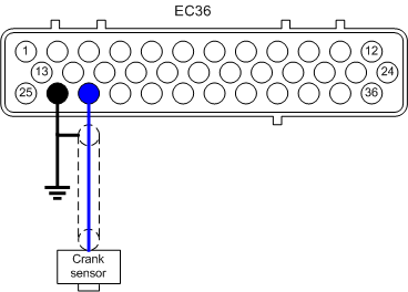
Primary VR sensor
VR sensors have two wires (and often a 3rd (shield)). The polarity must be known. If polarity is reversed, triggering will be erratic or may not occur at all. VR sensors are susceptible to noise during craking, when RPM is low (which means the VR signal amplitude is low). Cable with 2 wires + shield is strongly recommended.
- EC36-pin27 VR+ (wire1)
- EC36-pin26 VR- (wire2; also connected to shield at the ECU end of the VR cable)
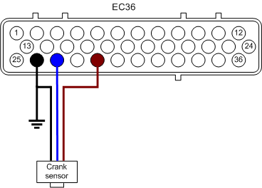
Primary Hall sensor
Hall sensors are attached the same way as VR sensors, except they need a switched +5VDC (rarely +12VDC) supply. The same supply voltage that is used for Genboard v3 can be used to power the Hall sensor if it is a 12V model. If the Hall sensor is a 5V model, it can use the +5VDC supply from Genboard at EC36-pin28.
- EC36-pin27 Hall signal
- EC36-pin26 Ground
- EC36-pin28 +5V
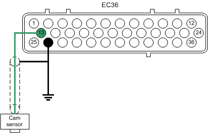
Secondary VR sensor
- EC18-pin12 VR+ (yes, EC18-pin12 !!! HW must be set up for auditrigger configuration)
- EC36-pin26 VR- (shield and ground)
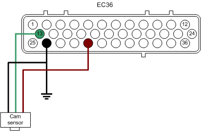
Secondary Hall sensor
- EC36-pin13 Hall signal (If HW was accidentally ordered with "auditrigger" configuration, and secondary trigger is HALL only, a solderblob from the bottom of v3.3 must be removed to prevent the 2nd LM1815 chip from interfering!)
- EC36-pin26 Ground
- EC36-pin28 +5V
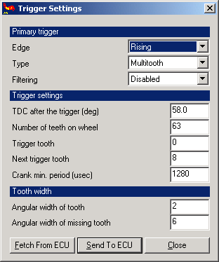
The primary trigger is configured in the 'Trigger Settings' dialog which can be found in the main menu 'Settings->Trigger Settings'.
-
Primary trigger
-
Edge
When using a VR sensor the ECU must be configured to trigger on the rising edge of a tooth.
-
Type
Two types of trigger wheels are supported, either the missing tooth (multitooth) layout or a symetric coil-type.
-
Filtering
When using a coil-type wheel it is sometimes nessecary to enable filtering in order to get a good clean trigger signal. In case a multitooth wheel is used, filtering must always be disabled, otherwise erratic RPM signal might occur.
-
| VR/toothed wheel | Hall | |||
|---|---|---|---|---|
| Edge | Rising | ? | ||
| Type | Multitooth | ? | ||
| Filtering | Disabled | ? |
Table 9.1. Trigger Settings
-
Trigger settings
-
TDC after the trigger
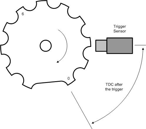
It is very important that the 'TDC after the trigger' value is configured correctly. The value of 'TDC after the trigger' must be between 40 and 60 degrees. Before attempting to configure it the two values 'Trigger tooth' and 'Next trigger tooth' must be determined and configured properly, unless a coil-type trigger wheel is used.
In the example shown in Figure 9.6, “TDC after the trigger, 12-1 trigger wheel example” 'Trigger tooth' is set to 0 and 'Next trigger tooth' is 6.
The value of 'TDC after the trigger' can be roughly measured with a degree wheel. Position the number one cylinder at TDC and measure the angle as shown in Figure 9.6, “TDC after the trigger, 12-1 trigger wheel example” . If the measured angle is outside the range of 40-60 degrees, the value of 'Trigger tooth' must be adjusted to compensate.
It is nessecary to fine tune 'TDC after the trigger' once the engine has been started up (see Section 9.1.5, “Calibrating - TODO” ).
Coil-type trigger wheels are configured in the excact same way, measure angle and calibrate as described in Section 9.1.5, “Calibrating - TODO” ).
-
Number of teeth on the wheel
For multitooth wheels the actual number of teeth must be known. The easiest way to determine this values is by counting the actual number of teeth on the wheel.
Alternatively this number can be calculated if the specs for the multitooth wheel is known.
Number of teeth on the wheel = imaginary teeth - missing teeth
Example #1: 12-1 wheel
12 - 1 = 11
Example #2: 60-2 wheel
60 - 2 = 58
-
Trigger tooth
Tooth numbering begins at zero on the first tooth past the missing tooth, in the direction that the toothed wheel is rotating.
-
Next trigger tooth
Normally one event is required per cylinder on an engine. The value of 'Next trigger tooth' reflects that. It can be calculated using the following formula:
Next trigger tooth = imaginary teeth * 2 / number of cylinders
Example #1: 12-1 wheel, 4 cylinders
Next trigger tooth = 12 * 2 / 4 = 6
Example #2: 60-2 wheel, 4 cylinders
Next trigger tooth = 60 * 2 / 4 = 30
Example #3: 60-2 wheel, 6 cylinders
Next trigger tooth = 60 * 2 / 6 = 20
-
Crank min. period
In order to filter out noise from the trigger the 'Crank min. period' value must be determined. It is very important that the configured value is higher that what is expected during normal running conditions near the rev limiter.
Using the formula below it is possible calculate a reasonable 'crank min. period' value:
Crank min. period = 60 sec / max RPM / number of engine events * 2
Example #1: 14000 rev limit, 4 cylinders
Crank min. period = 60 sec / 15000 / 4 * 2 = 0,002 sec = 2000 usec
Example #2: 7000 rev limit, 6 cylinders
Crank min. period = 60 sec / 8000 / 6 * 2 = 0,0025 sec = 2500 usec
A safety margin between the rev limiter and the value used in the calculation is a good idea, hence the additional 1000 RPM.
-
-
Tooth width
The 'Tooth width' section is only applicable when using a multitooth wheel. VERY IMPORTANT: Unfortunately the width of teeth in this section is NOT in real degrees.
A list of the most common multitooth trigger wheels can be seen in Table 9.1, “Trigger Settings” .
Type Angular width of tooth Angular width of missing tooth Engine phase 12-1 10 20 240 24-1 5 10 240 36-1 3 6 216 60-2 2 6 240 Table 9.2. Common trigger wheel values
Settings for other multitooth trigger wheels can be calculated as described below.
-
Angular width of tooth
An entire engine cycle of 720 (real) degrees must be scaled down to no more than 255 (decimal). The easiest way to accomplish that is to used the following formula:
dec = 255 / (2 * imaginary teeth)
The value dec must be an integer so it must always be rounded down.
Example #1: 12-1 wheel:
dec = 255 / (2 * 12) = 10.625 = 10
Example #2: 60-2 wheel:
dec = 255 / (2 * 60) = 2.125 = 2
Before any angular width values can be calculated, the engine's phase must be determined.
Engine phase values for unlisted trigger wheels can be calculated using the following formula:
Engine phase = 2 * (dec * real teeth + dec * missing teeth)
Example #1: 12-1 wheel:
Engine phase = 2 * (10 * 11 + 10 * 1) = 240
Example #2: 60-2 wheel:
Engine phase = 2 * (2 * 58 + 2 * 2) = 240
Calculating 'Angular width of tooth' is easy using the formula below:
Angular width of tooth = engine phase / ( imaginary teeth * 2 )
Example #1: 12-1 wheel
Angular width of tooth = 240 / ( 12 * 2 ) = 10
Example #2: 60-2 wheel
Angular width of tooth = 240 / ( 60 * 2 ) = 2
-
Angular width of missing tooth
When the field 'Angular width of tooth' has been determined it is very easy to calculate this field.
Angular width of missing tooth = (missing teeth + 1) * dec
Example #1: 12-1 wheel
Angular width of missing tooth = (1 + 1) * 10 = 20
Example #2: 60-2 wheel
Angular width of missing tooth = (2 + 1) * 2 = 6
-
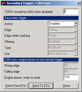
The secondary trigger is configured in the 'Secondary Trigger/Cam sync Settings' dialog which can be found in the main menu 'Settings->Secondary Trigger/Cam sync Settings'. TODO: merge from http://www.vems.hu/wiki/index.php?page=Genboard%2FManual%2FInputTriggerCamSync
VR sensor
| Variable Name | Value | Units | Description |
|---|---|---|---|
| primary_trigger | 0x01 | Use 0x01 for toothed wheel (and VR sensor). | |
| tooth_wheel | 0x23 (35) | 0x01=1 tooth | Total number of teeth on wheel. Use 0x23 for 36-1, 0x3A for 60-2. |
| tooth_wheel_twidth1 | 0x0A (10) | 0x01=1 degree | Width of single tooth on wheel, in degrees. |
| trigger_tooth | 0x01 (1) | 0x01=1 tooth | Number of tooth which triggers an event; missing tooth is number zero, 1st tooth after missing tooth is number 1, etc. First tooth after missing teeth on 60-2 wheel is number 2. |
| secondary_trigger | 0x1D | Use 0xFE for rising edge trigger, 0xFF for falling edge trigger, 0x01 for toothed wheel, 0x1D for rising edge, enable, enable filtering, coil type, cam sync, single edge, 0x02 if NOT using camsync. If 0x02 is not used here while not using camsync, you will have neither spark nor fuel! | |
| another_trigger_tooth | 0x12 (18) | 0x01=1 tooth | Trigger tooth for secondary trigger device. Use 0x06 for 12-1 and 4 cyl, 0x1E for 60-2 and 4 cyl, 0x14 60-2 and 6 cyl, 0x12 for 36-1 and 4 cyl. |
| tooth_wheel_twidth2 | 0x06 (6) | 0x01=1 degree | Width of one tooth on the secondary trigger wheel, in degrees. |
| cam_sync_r_edge_phase | 0xFF (255) |
Table 9.3. VR sensor configuration
How to calibrate ign_tdcdelay. Set crank advance to 0 and adjust with timing light.