The wideband oxygen sensor is the engine tuner's best friend. A narrowband sensor is next to useless to tell air-fuel ratio where you need it the most: loadsites where the engine must run rich so it does not blow up. Also, when ignition advance is changed, the fuel must be adjusted too. This is a very time and nerve-consuming task to do manually. Genboard's extremely precise WBO2 controller can do it amazingly fast (~80msec time-constant).
The wideband oxygen sensor ust be located before the catalytic converter if present. Ideally the WBO2 sensor should be placed as close as possible after the collector, rule of thumb is 70-100 cm after the exhaust port. The sensor must not be placed to close to the exhaust tip as it might get false readings from the surrounding fresh air. Take care not to place the wires to close to the hot exhaust pipe.
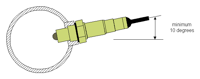
Ideally the oxygen sensor should be mounted as pictured in Figure 9.18, “Physical mounting of the wideband oxygen sensor” . When mounted with a small inclination then sensor becomes self cleaning in terms of carbon build up.
All oxygen sensors use 18x1.5mm threads, if the vehicle is equipped with e.g. a narrowband sensor the existing mount point can be reused. If the vehicle doesn't have an oxygen sensor, a suitable location must be found as mentioned above. Drill a hole in the exhaust system and weld a nut or boss on it.
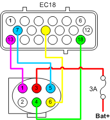
The wide band sensor's plug is connected to VEMS though the EC18 connector, the following schematic gives the pin connections. Make sure you use a fuse when connecting the wideband sensor to its power supply. It is recommended to use a 3A automotive fuse.
- EC18-pin13 to WB6-pin1 Nerst Cell Signal
- EC18-pin7 to WB6-pin5 WBO2 Pump-
- EC18-pin18 to WB6-pin4 Heater
- EC18-pin9 to WB6-pin6 WBO2 Pump+
A wideband oxygen sensor is a complex device, and it is controlled by many paramters.
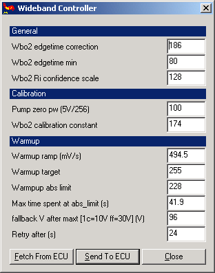
First the sensor most be configured in the dialog 'Wideband Controller', which can be found be selecting 'Settings->Wideband Settings' from the main menu (see Figure 9.20, “MegaTune - Wideband Controller dialog” ).
-
General
-
Calibration
-
Pump zero pw
The pump must be calibrated for correct operation, this process is described in Section 9.6.6.1, “Pump zero pw calibration” . When purchasing a Genboard the 'Pump zero pw' value found during final test and verification is listed on the invoice.
-
Wbo2 calibration constant
- TODO
-
-
Warmup
-
Warmup ramp
- TODO
-
Warmup target
- TODO
-
Warmup abs limit
- TODO
-
Max time spent at abs limit
- TODO
-
Fallback V after maxt
- TODO
-
Retry after
In case the warmup of the sensor fail for some reason, a new attempt to heat it will be executed later. The time value can be set in 4 second intervals, a reasonable value would be in the 12-24 second range.
-
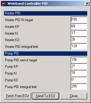
Secondly the sensors PID must be configured in the dialog 'Wideband Controller PID', which can be found be selecting 'Settings->Wideband Controller PID' from the main menu (see Figure 9.21, “MegaTune - Wideband Controller PID dialog” ).
| Variable Name | Starting point value | Units | Description |
|---|---|---|---|
| ego_conf | 0x07 (7) | EGO configuration. Use 0x07 if you are using a WBO2 sensor. | |
| wbo2_warmup_ramp | 0xA0 (160) | 0x01=0.2V/sec | Rate at which voltage is increased to the WBO2 heater. |
| wbo2_abs_limit | 0xE4 (228) | 0x2A=12V 0xFF=30V | WBO2 heater upper voltage limit. |
| wbo2_limit_maxt | 0xA0 (160) | 0x01=262msec | Max time to spend at WBO2 heater upper voltage limit. |
| wbo2_fallback | 0x60 (96) | TODO: 0x01=? | Voltage to fall back to after spending wbo2_limit_maxt time at wbo2_abs_limit. |
| wbo2_retry_t | 0x06 (6) | 0x01=262msec | Retry applying heater after this amount of time. |
| wbo2_edgetime_corr | 0xBA (186) | Edgetime correction constant. Filters noise out of WBO2 signal. Don't change. | |
| wbo2_edgetime_min | 0x50 (80) | 0x01=0.5usec | Edgetime minimum length. Filters very short edgetimes out of WBO2 signal. You shouldn't need to change this. |
| wbo2_calibration | 0xB0 (176) | WBO2 sensor calibration. Differs for every sensor. Adjust until O2% on mlp07 is 20.95% | |
| wbo2_pump_pw_zero | 0x64 (100) | Pump zero duty cycle trim. Adjust (usually +-1 ) so that voltage between pump+ and pump- is closest to zero volts. | |
| wbo2_ri_target | 0x96 (150) | Pulse amplitude trim. | |
| wbo2_nernstdc_target | 0x8D (141) | Nernst voltage trim. | |
| wbo2_ri_confidence_scale | 0x80 (128) | Ri confidence scaling factor. | |
| wbo2_heater_pid_kp | 0x45 (69) | ||
| wbo2_heater_pid_ki | 0x11 (17) | ||
| wbo2_heater_pid_kd | 0x1A (26) | ||
| wbo2_heater_pid_ilimit | 0x81 (129) | WBO2 heater PID integral limit. | |
| wbo2_pump_pid_kp | 0x15 (21) | ||
| wbo2_pump_pid_ki | 0x4e (78) | ||
| wbo2_pump_pid_kd | 0x00 (0) | ||
| wbo2_pump_pid_ilimit | 0xFF (255) | ||
| ego_coolant | 0x92 (146) | TODO: 0x01=? | Minimum coolant temp for EGO correction enabling. |
| ego_maxtps | 0xFF (255) | 0x01=0.4% open | Max TPS position for EGO correction enabling. |
| ego_maxmap | 0xFF (255) | 0x01=0.4% | Max MAP pressure for EGO correction enabling. |
| ego_minrpm | 0x08 (8) | 0x01=100rpm | Minimum engine speed for EGO correction enabling. |
| ego_maxrpm | 0xFF (255) | 0x01=100rpm | Max engine speed for EGO correction enabling. |
| ego_lean_limit | 0x30 (48) | 0x01=0.4% | Max percent of AFR enrichment allowed. |
| ego_rich_limit | 0x80 (128) | 0x01=0.4% | Max percent of AFR enrichment allowed. |
| wbo2_warmup_target | 0xFF (255) | Unused. |
Table 9.4. WBO2 sensor config variables
It is very important that the wideband oxygen sensor is calibrated carefully and correct. An uncalibrated sensor might lead to false readings and worstcase a broken engine. The calibration is not complicated, and it must be carried out once. If the sensor is replaced later on it is highly recommended that the 'free air' calibration is repeated.
Before the wideband oxygen sensor is plugged into the wiring harness the 'Pump zero pw' must be calibrated.
It is very important that the sensor heater is not turned on, either manually or accidently. If trigger events occur the Genboard module will turn on the sensor heater automatically.
Connect the RS232 interface and start MegaTune, power up the Genboard module. Attach a DVM to the wideband connectors pin 5 and 6 and measure the voltage. The ideal voltage is 0v, obviosly the goal is to get as close as possible to that. The voltage can be adjusted in the 'Wideband Controller' dialog (see Figure 9.22, “MegaTune - Calibrating 'Pump zero pw'” ), select 'Settings->Wideband Settings' from the main menu.
TODO Adjust until correct, 98-102? Can also be found in the mail from the webshop.
The final setting we need to make is to wbo2_calibration:
- Attach the WBO2 sensor to the wiring harness of Genboard v3
- Power up the board and change to LCD display page 7
- Enable the WBO2 heater by typing "mde02". Wait for the O2% to show a reading.
- Adjust wbo2_calibration until the O2% reads 2095 (read 20.95%, the amount of oxygen in free air). Don't forget that each time wbo2_calibration is changed, you must re-"make" config.mtt and upload it via your terminal program to Genboard v3.
-------
Type Manmlp07 to get to the AFR screen. The LCD screen should show something like:
Ri:0000 Nernst:0000
Heat:00 Pump:65
AFR=? 02%=?
AFR=08.29 OFF
Sending the command "mde02" will turn on the WBO2 heater. Sending "mde00" will turn the WBO2 heater off.