Genboard v3 uses a GM IAT sensor as standard, but can be configured to use any NTC type resistive sensor. The GM IAT sensor is available in the WebShop, and many other places for very cheap.
Intake air temperature is the second most important sensor in a speed density based system. The intake air temperature is used for calculating the density of the air, which is essential when calculating the required amount of fuel.
The IAT sensor is very prone to heat soaking since it is so close the engine. Heat soak is a situation when the sensor is heated by the temperature of the engine itself to the point that it cannot properly read the temperature of the air entering the engine.
The obvious solution would be to install the IAT sensor as far upstream from the engine as possible; unfortunately the air is heated when going through the intake manifold. The nature of the speed density system makes it interesting to know the temperature when the air passes over the throttle blade and when it passes the intake valve. A bunch of factors makes it more important to read the temperature close to the intake valve.
It is very essential that fuel does not get on the temperature sensor! Fuel vaporizing on the sensor will effectively cool it to below the actual intake air temperature, consequently the sensor must sit before all injectors. Another important thing to consider is the fact that hot cams often make the engine spit fuel backwards up the intake tract.
Recommendations about IAT sensor placement:
- Throttle body injection: Place sensor before throttle body.
- Port injected with one throttle body and plenum. Place IAT sensor in one of the intake runners.
- Port injected with one throttle body, plenum and a hot camshaft: Place IAT sensor in the common plenum.
- Individual throttle bodies: Place IAT sensor upstream of the throttle blade (Individual throttle bodies is often used together with a hot camshaft).
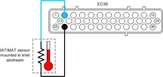
The intake air temperature sensor must be wired up according to the diagram below.
- EC36-pin2 Signal
- EC36-pin26 Ground (also ground to the engine block close to sensor)
It is not possible to configure the IAT sensor, it is only required that it is calibrated correctly (see Section 9.3.5, “Calibrating - TODO” ).
After the IAT has been configured it is a very good idea to test the sensor. The easiest way to test the sensor is to use three known temperatures.
- Ambient room temperature, use a normal thermometer as reference.
- Boiling water at sealevel should be very close to 100C.
- Ice water, a glass of water stirred with some ice cubes should be very close to 0C.
Connect the Genboard module to a PC with a serial cable and start MegaTune and check the readings.