11th January 07
Hi every one.
This VEMS is being constructed to replace the now useless Rover MEMS1.9 ECU on my Group A rally spec Classic Mini.
A Little History
The engine is a Single Point Injected, standard stroke, 74mm bore transverse Rover 'A' series engine http://www.austin-rover.co.uk/engineaseriesf.htm . Everything was running well enough before fitting the Ex works ( http://www.wpm.co.uk/worksminis/ ) group A cylinder head, which this particular head from the BMH ( http://www.bmh-ltd.com/ )prepaired cars, had seen and completed the Monte Carlo Rally and the Nurburgring. This head pushed the compression ratio further from the original CR that the MEMS ECU had ignition maps for.
This problem was evident when I first built the engine when the CR went from the factory 9.4:1 to 10.5:1. Onset of knock was evident on 95 octane unleaded and just about normal on 99 octane. So I knew something had to be done when calculating the CR with this head to be 11.2:1.
What i did to try and overcome the problem of knock was to remove he reluctor ring on the flywheel, retard it by X amount of degrees and re install it, thus retarding the ignition advance right across the map
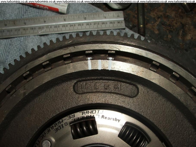
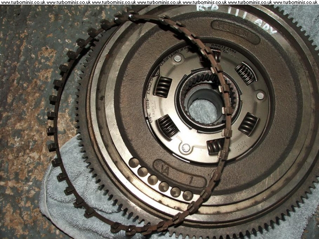
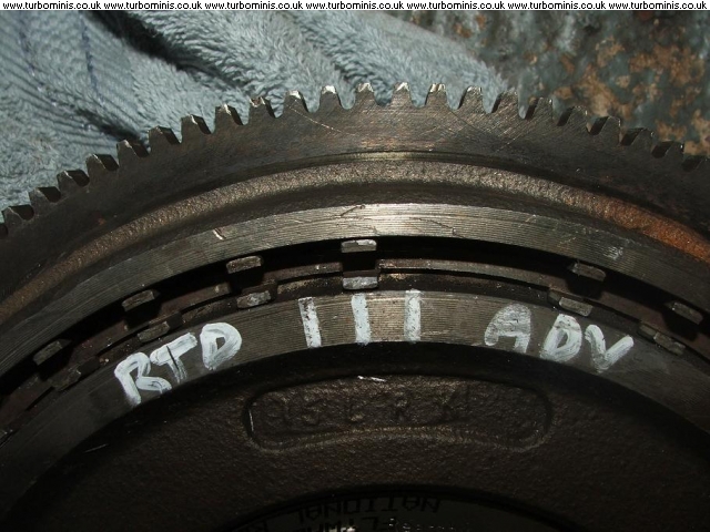
This was good in theory, and probibly still good if you dont retard by too many degrees, as I found out!
I retarded by five degrees, not realy knowing that the cold crank degrees is set to 5. So, cold starting on a cold, rainy winters day, its a bitch to start to say the least. I retarded by too many degrees. once the engine is running its fine, though suspect that its not performing as it should.
This is where VEMS comes in. To bin the MEMS and replace with a programable ECU and still start, run and drive as though it were a factory ECU for minimal cost. Megasquirt had always been considered, but a fellow TurboMinis ( http://www.turbominis.co.uk/forums/index.php ) member posted about VEMS. I was curious, and, well, here I am.
Hoping this is going to be a very exciting project unvaling that lost power of my engine.
Baisic spec of the Engine Management System
Unipolar Stepper Motor ( more to come on this, I have been researching for some time using Unipolar motors as Bipolar)
Throttle body single point injector, Low Z
Knock detection (mainly for the future turbo engine, experimental at this stage)
Wideband Lambda
EGT (mainly for the future turbo engine, experimental at this stage)
Original coolant temp sensor
Original Air temp sensor
DIS coil pack from an MPi Classic Mini ( ditching the dizzy and coil)
Original crank angle sensor ( reluctor modified to give 36 -1)
I am going to butcher and modify a factory engine loom and hybred it with an engine loom from a late Rover 820 Turbo with DIS and mount the ECU inside the car
13th January 07
This is the salvaged Rover MEMS case that i have decided to use. The middle section needs the original heat sink bars removing to give a little more working space.

Locating the GenBoard towards the back of the case using 10mm isolating stand offs, thus still allowing for heat sinking of the components and also room for the MAP sensor. The Econoseal plugs will be in the same orientation in the case as they would be on the GenBoard, connecting the two with wire. All bare terminals/ connections will be insulated with resin filled heat shrink.
Q. Hoping to put Flyback Diode in this connecting wire - Econoseal Flyback pin to GenBoard. Please confirm this is an acceptable idea? Aparently this is acceptable, so has been done, see below for picture.

Looking to put the serial connection 'D connector' through the case some where, for easy connection to the computer.
This is how the finished ECU should look with the D connector on the bottom or the back. All will eventualy be sealed.

Next update will be on the GenBoard itself
V3.3 GenBoard Flyback path:

Stepper IC orientation:

The 10uF (1210 size, 35V) capacitor was already installed (not in the rescue kit 2):

The transient supression diode (max 36V) is installed with (stripe-marked) cathode connected to the onboard flyback rail; the anode to the injector common (+12V). Our standard is 30V bidirectional that is easier to install (works in either direction)

DONE, replace ground reinforcement wire, re route better. Burning mark on isulation only, no shorts. Just to tidy up.
DONE, clip back wire tails at solder pads
DONE,(actualy replaced individual pads with a sheet) two IGBT insulator pads required before final install of GenBoard in the case. only bought ten where twelve required.
DONE, IGBT/FET case clamps.
TODO, connect MAP to port on case.
Board wiring is standard. (with minor exception: RS232 obviously connected to it's own DSUB9 connector, not EC18pin14 and EC18pin15)

View of GenBoard installed in case with wiring and modified Econoseal connectors.

DONE,buy a 25watt solder iron and replace on board flyback wire. Just to tidy up.
View of top of case with serial port.

DONE cut holes in case top for PS/2 and Dsub9 ports for keyboard and LCD.
Off topic slightly.
Can any one please tell me which EC36/18 pins are discrete inputs. Advanced AntiLagSystem control parameters in MegaTune 2.25 states input chanel 0 to 7, obviously for enable disable switch. Where do I wire this in??
May be a daft question??
MembersPage/PhatBob There are no daft questions only daft answers. The spare analog channels are used with a resistor - the exact wiring of which escapes me for the moment, I was to put it in MembersPage/PhatBob/UserGuide
Is there a list of input chanels and related EC36/18 pins??? I cannot find it if there is.
I have a dilema with which injection sequence to use on port injection. I have two sets of injectors off the same model car but different years. One set are half the CC of the others and batch fired in pairs alternately (two squirts per cycle). The larger CC injectors are fired sequentialy (one squirt per cycle)
Question ? whith the above information, which set up would give better idle characteristics? This is a small CC engine at 1275 with very large injectors for this capacity. Needed for max output of between 150 and 180bhp. I am considering the smaller injectors on batch fire, i have an injector loom already for this, and would also free up two other FETs for the water pump and cooling fan.
MembersPage/PhatBob Firing individually is the best bet you shouldnt need the additional FETs to drive the relays because they've got the p259 chip.
BTW can you email me please: rob@vems.co.uk thanks.
On topic.
Currently waiting on some parts to finnish off ECU, so, pulling appart the two engine wiring looms I have, one from a Mini and the other from a Rover 820 turbo. Connectors and screened wires already terminated, making it that bit easier.