| [Start] | [Questions ] | [ Injector] | [Ignition] | [Triger] | [Display] | [Wbo2] | [Config] | [Table] | [Wiring] |
Wiring
All grounds MUST ground to the same point. Please review the MembersPage/PhatBob/UserGuide and read the grounding section.
- Make your wiring with Corel Draw just download the
EC36pin5, EC36pin21 and EC36pin32 are all the same ground (GND5), where all "output"-transistors are mounted to (= noice/disturbances). Ground to sensors should be connected to EC36pin26, where the ECU are mounted to, and so close to the battery as posible to avoid noice. Regards HansK?
Note that the sensor GND (EC36pin26) should be used for sensors instead of the powerGND
- showstopper for trigger
- showstopper for knock
- serious TPSdot noise on TPS (TPS-accel engaged unintentionally)
- some measurement error on temperature sensors
VERY important: the current that goes to the powergnd pins (=GND5, that is EC36pin5, EC36pin21, EC36pin32 and often EC36pin22 is also used for GND5, when EC36pin22 airwired inside the ECM to GND5 plane) must NOT effect the sensor-GND. That suggests to use separate wireS (yes, not one but 3..4 wires as independent as possible, only connect very near the battery), not sharing path with sensor-GND.
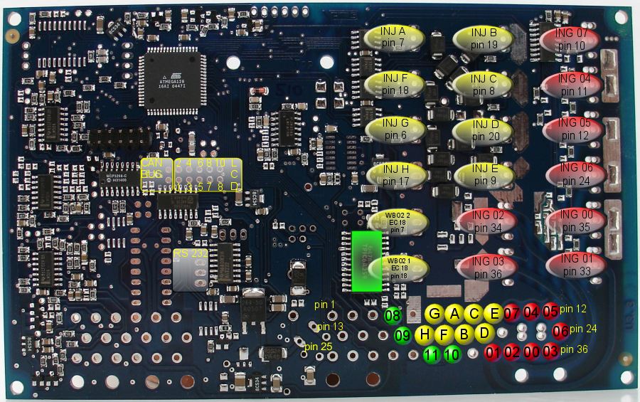
- serious: "injector common" (inj +, red) must always (even if all fuses break!) be connected to the flyback rail. Flyback rail is normally EC36-pin23, but might be EC36pin22 in your case if you assembled the ECM and chose to connect the airwire to EC36pin22. A quick DVM measurement in diode mode will tell: injector output to flyrail is appr 600..1100mV.