Engine basic info
- nr of cylinders (?!!!)
- firing order (?)
- other basic info about engine ?
- [Actual logs]
- [Current vemscfg.txt config]
Spark Event Problem
OK, VR Primary Trigger issue seems resolved with LPF.
But, I now have erratic spark events when firing with some fuel (down throttle body, injectors still off until it makes some noise):
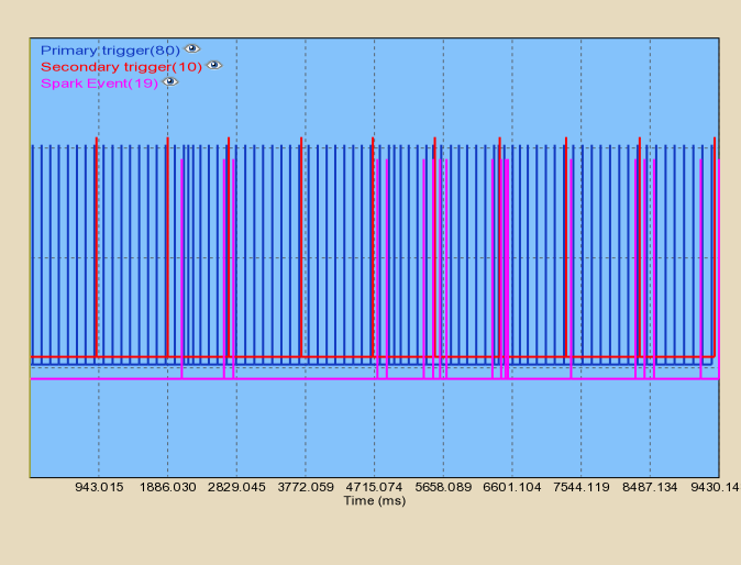
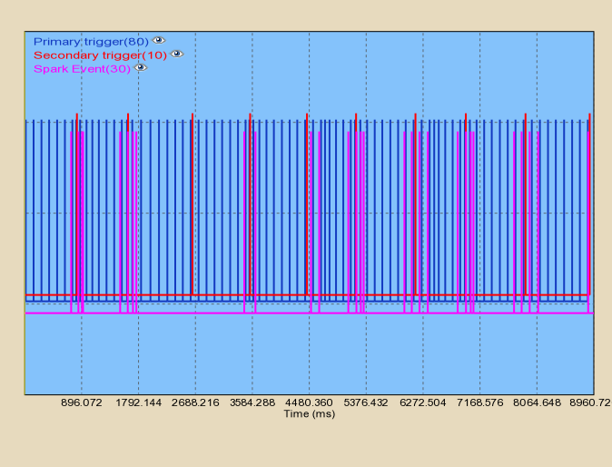
I have to work out why the spark events are not to a pattern.
Any ideas?
Trigger setup - fill this in and/or correct it (it's now impossible to review this page)
- trigger pattern c008 (8+1)
- 4 pins on crank (often used on 8 cyl engines)
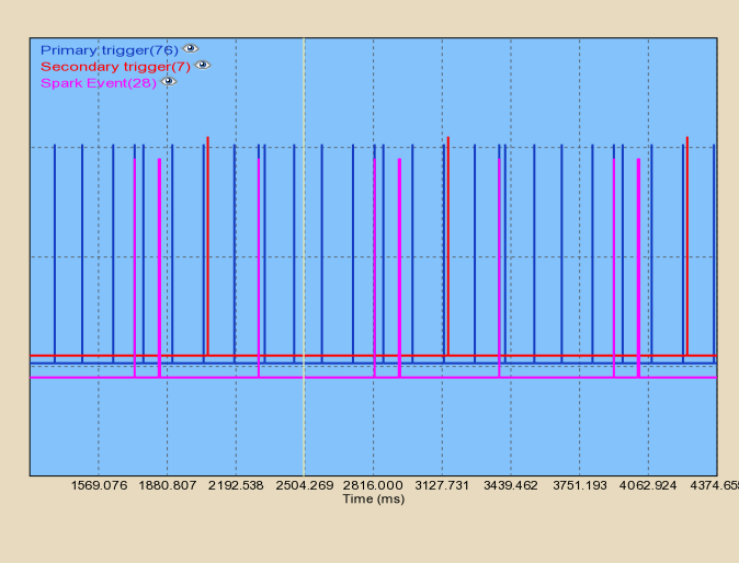
- 1 campulse - this must be well between the primary trigger pulses, but it can be seen in the log that position is too close to primtrig pulse, sometimes before, sometimes after (see the 7 primtrigpulses between 2 sectrigpulse ?)
- seems to be a good example of how home-made VR needs a lot of work and experience (only HALL is a good idea for home-made triggersetup)
- 'VR sensor resistance= 78 ohms (can you verify the measurement ? 78 Ohm is surprisingly low !)
- Answers to Qs previously posted:
- experienced installers recommend HALL sensor for any home-made trigger setup. There are very good reasons for this.
- I understand HALL would be ideal but this VR setup is what I have installed already with much custom machining, etc.
- is there a chance a HALL sensor would work with the wheel ?
- I doubt it. It is a very popular of the self product from MSD design for VR only.
- even with a VR sensor (which is just a very bad idea for a home-made trigger setup), with that low pulsecount, you might just need a capacitor between the VR input and GND...
- like 47..100nF (*1k Ohm=appr 100 usec, so strobe the engine at a few different RPM to see what compensation is needed to prevent TDC getting "delayed" with higher RPM)
- OK, I soldered a 100nF cap across the EC36 pins....it's big so only just fits in there.
- Recorded more trigger logs without noise! Success!
- Q: Is this the ideal value based on the seemingly low resistance of the sensor? ~20KHz low pass I think I have now.
- OK, I soldered a 100nF cap across the EC36 pins....it's big so only just fits in there.
- like 47..100nF (*1k Ohm=appr 100 usec, so strobe the engine at a few different RPM to see what compensation is needed to prevent TDC getting "delayed" with higher RPM)
Recommended trigger setup
- experienced installers recommend HALL sensor for any home-made trigger setup. There are very good reasons for this.
- is there a chance a HALL sensor would work with the wheel ?
- even with a VR sensor (which is just a very bad idea for a home-made trigger setup), with that low pulsecount, you might just need a capacitor between the VR input and GND...
- like 47..100nF (*1k Ohm=appr 100 usec, so strobe the engine at a few different RPM to see what compensation is needed to prevent TDC getting "delayed" with higher RPM)
- if that fails, can you try [VR to HALL adapter] near the VR sensor ? (important: request "set up signal without divider" in the order comment)
OK, the VR signal was infact reverse polarity.
- I have corrected and retested but the result is exactly the same. I have also recorded a new trigger log.
The trigger logs are interesting as the offending pri trig signal is shown 12us - 15us after the coil fires.
- This has been a constant in all trigger logs irrespective of VR polarity.
- it clearly indicates hardware interference (capacitive, or via ground)
I have re-routed all sensors and injector harness away from coils and ignition leads but it make no difference.
I have played with the VR harness shield (was grounded at ECU case with ECU floating) and that makes a big difference; floating - it generates irregular extra pri trig (1 - 3 per cycle), grounded to head - crazy with ~30 extra triggers per cycle.
- (fphil)I got Vems inputs less noisy when grounding the shields NOT at the ecu but at a good big ground. Could you not scope the incoming trigger signal while playing with the shields? Also the level from which the LM1815 trigs depends on the mode selected for that chip
I have a 100mm section of unshielded wire from VR harness to EC36, so I'll attempt to shield that too.
Now shielded
I shielded this section too which improved but I still get some noise (50% clean cycles, 50% with 1 or two extra Pri Trig signals.
So, the conclusion is that like many other trigger wheel setups, I need additional filtering in firmware - but that won't work in this case.
Please send me the 1.1.96 firmware code to spatrickb at hotmail dot com.
- if you have an algorithm-"skeleton" written in C (or perhaps some other language, but than it must be VERY simple and perfectly readable), running on PC (use the triggerlog pulsetrain as test-vectors) that successfully filters the offending pulses, we will consider it for inclusion in the firmware (it's non-trivial to apply).
- naiv code: filter one incoming pri-trig pulse that is 0-16 usec after coil fire. (if there are 2 pulses in this window, the 2nd can be considered the real pulse)
- problem1: Although there is hardware input-capture that captures quartz-precise timestamp in hardware, depending on interrupt latency it might not be able to tell if actually 1 or 2 (or more) pulses came a few microsec apart, only the fact that at least 1 pulse came in (it's perfect for any sane engine position sender: 38-40 usec is the minimum handled in 135-tooth auditrigger code around 14k RPM and for Nissan 360 pulse at 9000 RPM)
- problem2: if there is 1 pulse 0-16 usec after coil firing, it might be offending pulse or real pulse... so code must decide if a pulse was expected at this point. Even if it can decide, decision might be wrong (if it's a fake pulse but real pulse comes 50..100 usec later).
- conclusion: with a low-pulsecount trigger, the trigger signal should be good (fixed in hardware if necessary). If the signal can be moved so that real pulses really "clear" the spark points (even if using ALS or launch later ?), than it's theoretically (!!!) possible to filter, but more work than you think, and the good way is still to use a good trigger hardware setup like 100% of the working engines do.
I would like to simply filter them out with an algorithm that says "reject any pri trig signals within Xus (20us in my case) after spark event". As this window equates to only a few degrees at redline RPM, then the pickup position could be moved to allow.
Can someone please send me the 1.1.96 firmware code to spatrickb at hotmail dot com.
Continung InputTrigger issue
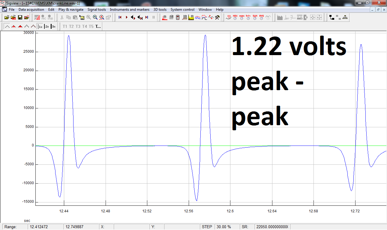
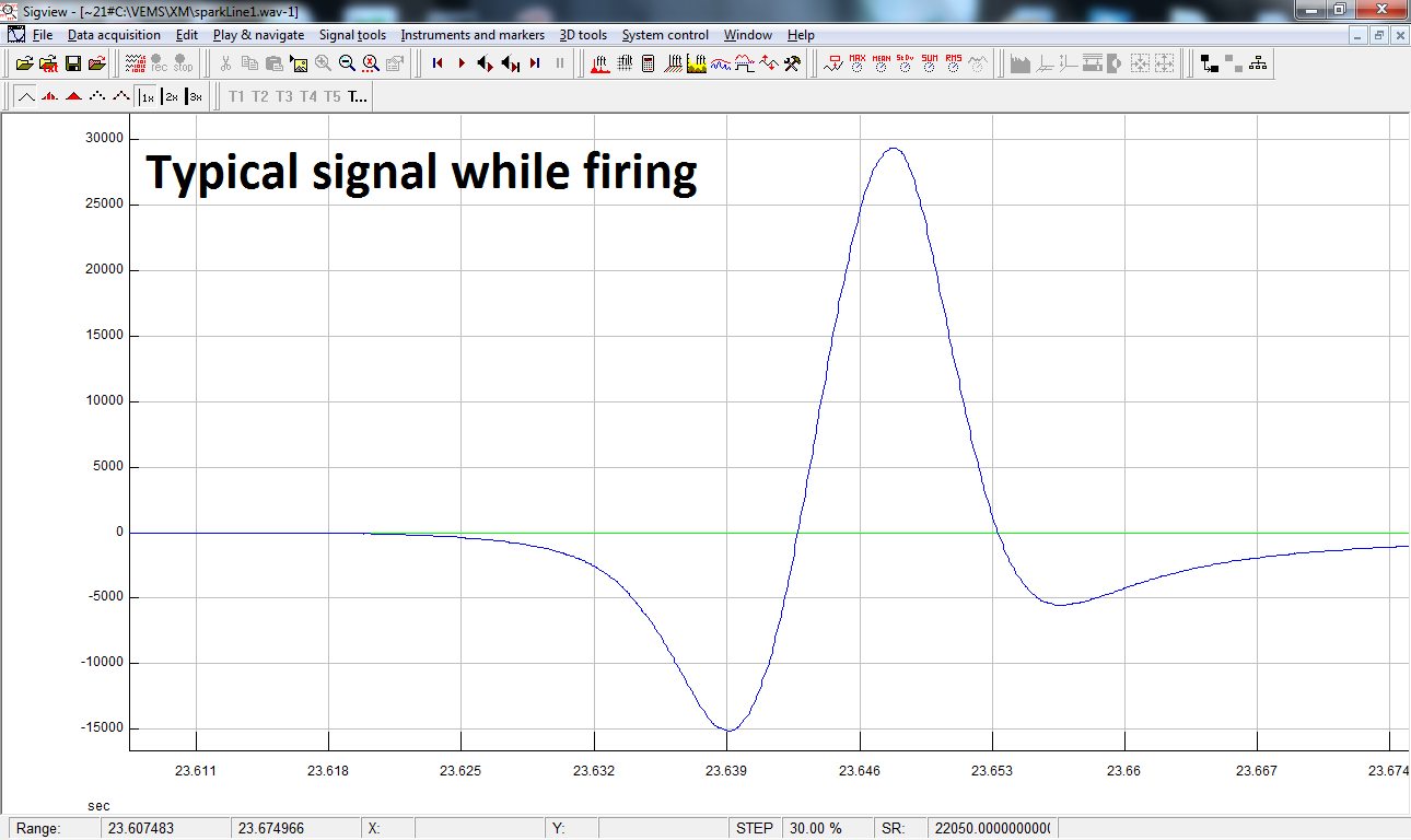
I recorded the signal into the line level audio input on my laptop. A bit crude but the signal looks to be VR, about 1.2 volts with a 0.02 variance. It is clean during coil firing and not firing.
These signal images show reverse polarity VR (rising edge, while LM1815 triggers on falling edge). Of course if the soundcard is inverting (some soundcard does), than it can be OK:
VR-polarity must be verified !
- scope
- or DVM and metal pulled from sensor + considering shape of wheel
- or applying a known polarity pulse to the soundcard to see if it's inverting or not, like a non-50% pulse like ignpulse (using logiclevel ign or IGBT and some pullup resistor >= 270 Ohm) with known conditions (RPM and dwell).
So, if the VR signal is clean, then the problem I think is either incorrect config or spark energy getting back into Genboard and causing to malfunction and report erroneous trigger errors. The injector harness and one or two sensor wires are very close to the coils, is that bad?
Any other ideas?
I'm Back
Wow, its been four years..started a family, etc....life gets in the way of playing with cars ;)
Anyway, I bought a v3.6 GenBoard for my latest project; a 302 CI Small Block Ford, EFI and Whipple Twin Screw Supercharger.
Everything works great except I have a VR Primary Trigger noise problem when coils are firing. Grounds are good, cable is shielded with MSD part # 8862, route is low on the block and along the brake lines with no electrics in path, polarity is correct, etc.
Are you sure it is VR sensor?
- for magnets, usually (3-wire) HALL sensor is applied
- [8640_add.pdf] suggests 2 wires, which is VR
- verify: measure resistance: if same resistance between 2 pins in both directions, (usually between 300-1400 Ohm) than it's VR
Logs here: http://vems.hu/files/PatrickB/PriTrigProblem/ (rename triggerlog*.txt to triggerlog*.triggerlog to view in VemsTune
They show that the signals are always clean and correct when coils are not powered (+12 relay removed).
However, the log gets 2 "Too Many Pri Trig" (MISSINGTOOTH errors?) per cycle when coils are powered. But, there are no missing teeth on wheel: http://www.msdignition.com/Products/Crank_Triggers/Crank_Triggers/8640_-_Ford_Small_Block_Crank_Trigger_Kit.aspx
It's just four flying magnets, one pulse per 90 degrees, hence the 8+1 config.
This problem manifests in sounding like it wants to start but then misfires/backfires.
My conclusion is that I have to live with this noise and filter it out in firmware.
The problem is I have tried all filtering options to no avail.
- can you capture (and publish) a scopeshot of the ANALOG (VR) signal when it's noisy ?
- amplitude is usually >1V (2V peak to peak) even during cranking
- If the sensor is 0.08" away from the wheel, try to move it closer (0.03") to improve signal/noise ratio
I am now ready to write filtering code unless someone has other suggestions.
- would be possible for a high-toothcount wheel (60-2, 36-1 or 36-2 or possibly even a 12-2) but not feasible for the 1 pulse every 90 crankdegrees (imagine the noise is close to the real signal: no way to decide which is the wicked one)
- if you capture analog signal and publish or link-from here, we can either have some good suggestion or send you [HALL sensor] for no charge (checkout with IBAN, order comment ...URL of this page...) for the experiments.
Old SVN stuff
You already got svn acc, if you cannot access for some reason, this is not something that can be resolved publically (for obvious reasons).
Old Trigger Problem with v3.1
Got the engine ready to go together and into the car so I've set up the GenBoard on my test engine but I have not yet been able to get a successful trigger config.
I am using a MSD Flying Magnet Crank Trigger http://www.msdignition.com/mag_1.htm
Describe the trigger PATTERN
I have the following config with v1.1.27:
primary_trigger=FE
tooth_wheel=4
tooth_wheel_twidth1=68
tooth_wheel_twidth2=00
trigger_tooth=0
This does not trigger at all.
- I have logged trigger output but it doesn't look right either
- the triggerlog must be good even if the config is bad. The triggerlog is just the timestamp of events.
- => not ready for investigating code. Measure and fix the trigger HW first. There is simply nothing to investigate in trigger config (or sourcecode) at this point.
Can someone tell me what is wrong with this config?
The problem is that the most basic things that need to be checked for any VR trigger are not all checked:
- What's the trigger pattern ?
- What is the polarity ? Is it OK for falling edge ? The link you provided suggests rising edge (not good)
- what is the measured sensor resistance ?
- What is the DC voltage bias ?
Background
I'm building a roots supercharged 347ci small block Ford (actually a stroked 302 Windsor) on which I wish to run an ion sensing ignition, so I'm looking at the GenBoard/VerThree (which is not yet implemented with IonSense, it needs some DCDC extensions even for simple CDI, but work is ongoing).
Goals
After spending a number of months researching ignition systems, i've decided that I want to use a non-commercial, ion sensing type ignition system for my current and likely future engine development projects. This is for a few reasons:
- All commercial ignition systems are completely proprietary, providing no options for third party software or hardware interfacing, thus having limited extensibility.
- I see ion sensing as a superior method for ignition monitoring and control.
- A system that I can build myself or build in collaboration, will be more cost effective.
Other functionality I want is:
- WBO2.
- Data logging.
- Supercharger efficiency monitoring.
- DetonationDetection.
- Both intelligent/dynamic or "dumb"/lookup table types of ignition control data.
- Loosely coupled hardware and I/O interfacing.
- 8ch EGT
Points 5 & 6 stem from racing regulations i.e. some racing classes do not permit the use of reactive electronics (computer control) but do permit other non-reactive electronics such as data logging, pre-programmed ignition curve, etc.
What's Next
OK, 4ch DIS off GenBoard is easy so it's all requirments met and I'm sold!
Now to start cutting some code...IonSense and/or JTune code.
Currently you can only play with IonSense sample-data on PC, as we don't have the LPC2119 playground yet (GenBoard/VerFour).
I added a MembersPage/PatrickB/Notes page for temp storage of thoughts, etc.
I've come up with a PPP detection algorithm that I've documented on the IonSense page. There's also a few other of my thoughts and comments on there.
I'm looking now to setup my own Ion Sensing test environment where I can collect more data to fine tune the algorithm then port it to ARM. Hopefully Jorgen is going to help me with a schematic for this.
I have my ADC/software ready for Ion Sense data collection and a chassis dyno to run on where I'll be able to run a number of conditions and collect a lot of data to use for fine tuning the algorithms. I plan to run idle, wot, detonation, accelerating, decelerating, highway crusing, etc. My friend should soon finish the hardware (current mirror, etc)...Stay tuned.
I've been hell busy at work and my friend has been sick for a couple of weeks but he should have the Ion Sensing test hardware completed by Sept. That'll tie in nicely with things cooling down at work, so expect Ion Sense to be cranked back into gear then!
BTW, got my v3.1 Just need the time now to put it together..another job for September.
My friend just sent me some CRO traces from his newly completed test ion sense circuit and they look very promising. :)
I'll arrange with him soon to take my car & DAQ along with his circuit to my friends chassis dyno where we'll run a number of tests and collect a lot of ion sense test data.
Went to my friends house and we hooked up the IonSense test circuit to my car and DAQ. We had some clipping problems so we had to play with the component values to get the right range (-5V to +5V), which we eventually did.
Collected a lot of data along the way but none of it is of any use yet, as we seem to be intermittently losing the ion current and this results in random chunks of waveform missing.
We think that this is perhaps due to the ion voltage being too low (it's about 300V) so we're going to setup another power supply of 400V and try that.
Digested the data collected in the last session and we've decided that the current in the current mirror test circuit is so low that the transistors may not be functioning correctly. My mate Gary is going to design a simple resistor based circuit as an alternative to the current mirror.
Here's a photo of my engine: 
It's nearly ready for final assembly....and a Genboard sticker ;
I've had some more ideas, I'd like to make this code run time conditional (as opposed to compile time conditional) based on a jumper setting perhaps, i.e. jumper on = race code, jumper off = standard/full featured code.
I also want to add to the race code:
- Upper rev limiting (set max revs via config, etc).
- Addtional 2 stage rev limiting (via config, etc) triggered by a single flip-floping momentary contact input, low-high = limit 1, low-high = limit 2, low-high = no limit (upper limit), low-high = limit 1, etc. Also needs corresponding output to led or similar to indicate current limit (upper only, 1 or 2).
- Shift point output for shift solenoid and/or shift light with configurable number of shift points.
Anyone know any theory/algorithms around ignition only rev limitng?
Well, it's been 18 months since I worked on this, during which time I was busy buying a house, etc. My car is not ready for the engine (and GenBoard) yet, but I worked on the IonSense project yesterday with my friend Gary.
We managed to record some IonSense signals!!! However, they have a lot of distortion from the ripple effect of the power supply. We are going to build a new low noise power supply to resolve that.
- The spark signal is apparently up to 50 times the magnitude of the pressure signal.
We are using an inductive ignition for testing at the moment, hence the need for clipping.
After we sort these problems, we will collect more data and design a circuit suitable for genboard interfacing.
GenBoard v3.1 Build
Started building my GenBoard....
- Added Power Supply,
- Tested Comms: OK.
- Added 4 IGBT for DummyIgnition - ordered MSD coils today, thanks for the help folks :)
- Added WBSensor (2 channels) - need to fully test.
- Added most of ExhaustGasTemp (2 channels). Check GenBoard/Manual/ExhaustGasTemp . 0..10 ohm is fine onto L4 pads (would be nice in RescueKit). AD597 GND to V- decoupling hint: 0..510 Ohm seems right (try 270 Ohm first).
- Finished EGT. I could not get a 10uH L4 in SMD so I used a full sized choke. Tested the board again and the trouble started....the current overloaded my multimeter and it read 0 so I hooked the board up direct (this was a very rude step!)....fizz and smoke, fried the choke!
- Finished the Knock circuit.
- HW finished!!
- Compiled and uploaded firmware. Tweaked the code beforehand as the LCD preprocessor directive did not work (I have no LCD).
Thanks,
Patrick B.