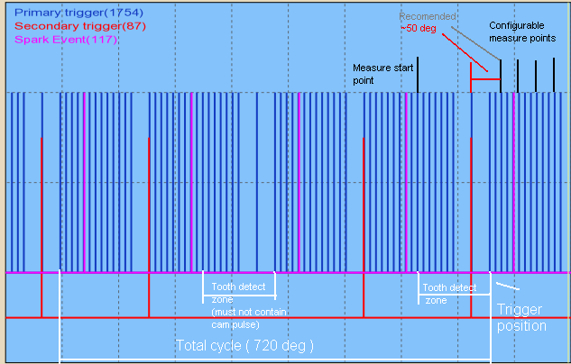
This 36-2-2-2 subaru trigger (like the missing-tooth triggers, or even none-missing tooth triggers) support sectrig-position (and third-trig position) measurement and therefore suitable for camshaft-angle-control (VVTI / AVCS). Just write here when you find out good
- measure tooth for sectrig
- measure tooth for third-trig
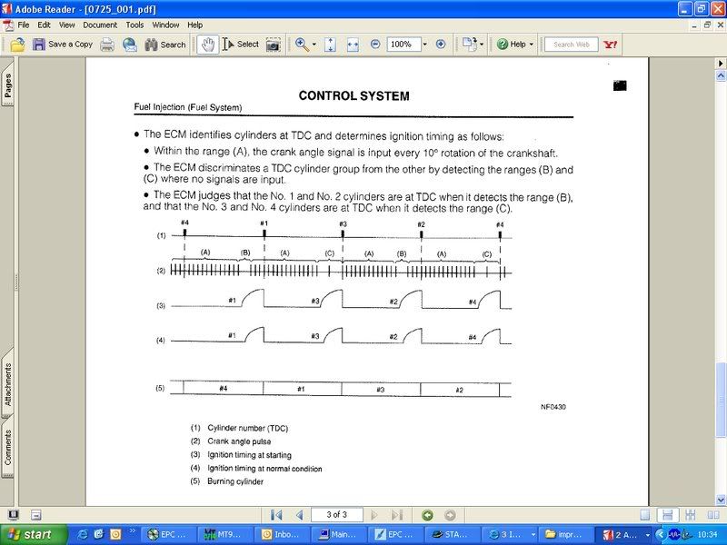
There is a contradiction about crank-pattern inside the Subaru manual (thanx for everyone contributing so we finally sorted it)
Cam info
There is a camsync pulse 45 crank degrees before Cyl 1 TDC, then the second comes 135 crank degrees after TDC
Camsync:
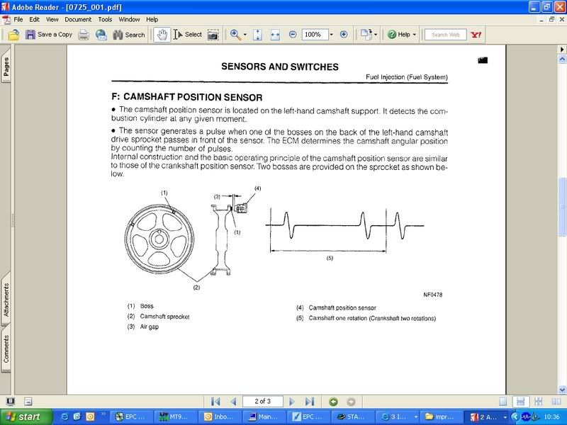
The relative position of the cam (having the camsync pulse coming inside the middle of the long gap) was a reasonable design decision.
Crank:
- 36-2-2-2 setup: 36 crank teeth
- missing 2 teeth BTDC Cyl 1 (long gap from 60 to 30 BTDC cyl1)
- and 2 teeth twice before BTDC Cyl 3. (long gap from 60 to 30 and 30 to 0 BTDC cyl3)
- Seen on North American 2.2L SOHC plants (99-01 model using 2 teeth cam wheel) as well as other 2.0L/2.5L Turbo plants (most using 4-1 cam wheel) ?????
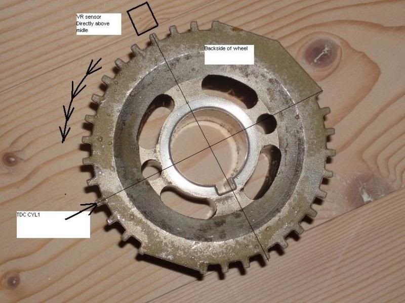
On both pics with the wheel, the wheel turns anti-clockwise. The engine runs clockwise, but the pic is of the back of the wheel.
The engine and the wheel physically turn clockwise, but the above photo shows the back of the wheel, so looking at the pic, the wheel turns counter clockwise.
That confirms: our implementation assumed the above photographed wheel rotates COUNTERCLOCKWISE so the double long gap is followed by 13 tooth, not 16.
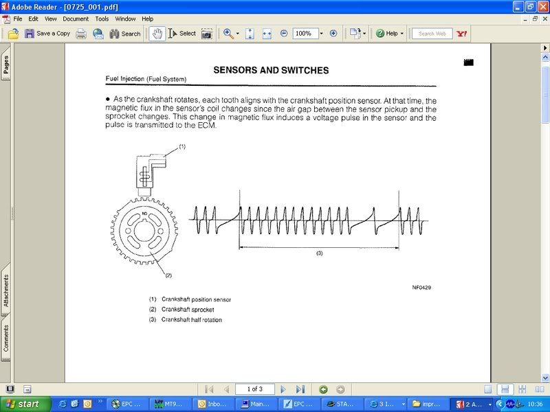
Crank Sensor wheel drawing, as mounted on the engine - rotates clockwise: (Beware: the plotted function is wrong: it shows a group of 13 teeth, instead of 16! This caused a lot of confusion)
just thinking
The choice to have the long gap detected at 30 BTDC and 0 TDC is weird.
- for fastest sync during cranking, 40 BTDC and 10 TDC would make most sense.
- for most precise timing during the whole range (and also for programmer's convenience) 90 BTDC and 60 BTDC would make most sense
We can look at it as 15+3,3+12+3
- TDC is 30 crankdegrees after the single missing gap
- in other words, TDC is the 4th tooth after the single long gap
Subaru 36-2-2-2 implemented with camsync: derived from c024 (12 cranktooth + 1 campulse)
H6 triggering
36-2-2-2 supported since early 2011.
- originally (13, missing, 16, missing, missing) ~ Subaru H4 sequence. secignore=62 (3E)
- from firmware 1.2.12 (19, missing, 10, missing,missing - this pattern is actually very different from the H4) ~ Subaru H6 pattern is also supported (most likely also other patterns of the same concept) with or without camsync (normally used with camsync).
- secignore=94 (hexa: 5E, or 5F)
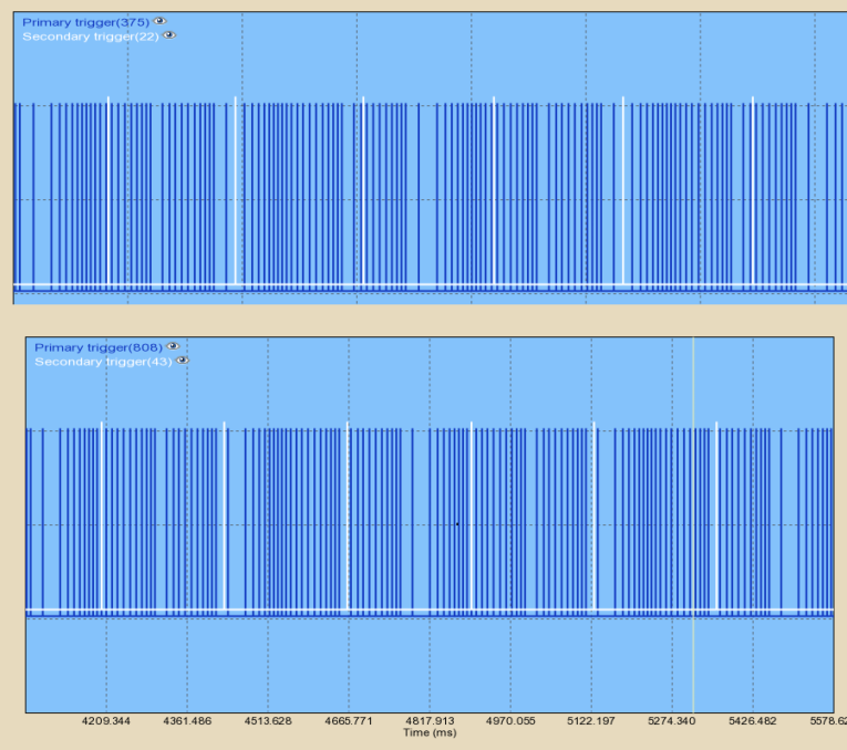
- very important: the edge (especially sectrig edge, if sectrig is used) must be selected to match the BOTTOM picture (no sectrig pulse must be within the 10-pulse primtrig-group). Is that Rising or falling edge ?
- Benchtest results: http://www.vems.hu/filethingie.php?action=list&subdir=GintsK/Subaru%20H6%20trigger/benchtest
- vvt subarus have two cam inputs
- newer engine with variable intake camshafts + VTEC-alike lobe switching use 3 evenly slots (240 crankdeg) on each camshaft.
- the non-vvt only have one camshaft
Here is two triggerlog files for old "dumb" H6 (== non-vvt ?). One file difference is falling/rising secondary (Hall type) captured some time ago.
http://www.vems.hu/files/GintsK/Subaru%20H6%20trigger/v3.3_n002316-2011-06-28-21.07.04.triggerlog
http://www.vems.hu/files/GintsK/Subaru%20H6%20trigger/v3.3_n002316-2011-06-28-21.15.54.triggerlog
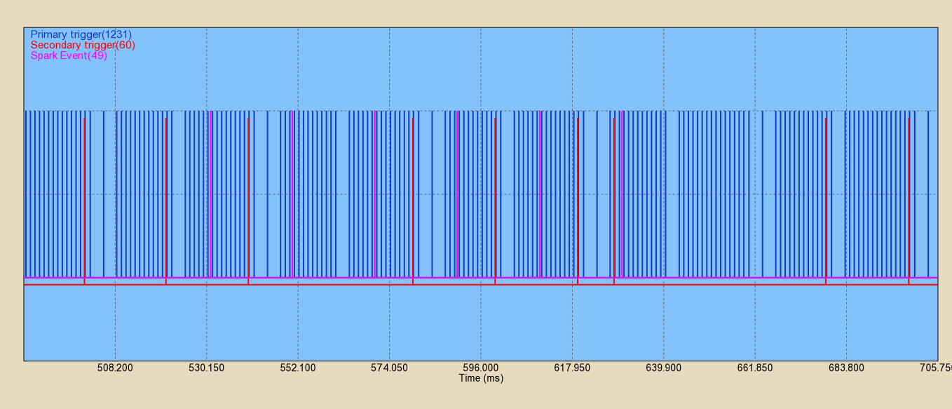
Picture shows difference between both above files:
This would be perfect for third-trig but somewhat suboptimal for sectrig because the pulse is very close to tooth0 (which is the [lonely tooth]. Could cause triggering problem (trigger error, misfire, etc...) if cambelt sloppiness causes signal to jump to the other side of tooth0.
Does 36-2-2-2 work For H6 engines?
- With no camsync?
- 2011-03-22 Yes, I ran the engine upon first startup with dualout and no camsync. Then a few minutes later changed it to camsync and sequential.
- for 1.1.96 or earlier, 36-2-2-2 without camsync was accidentally hijacked, see GenBoard/UnderDevelopment/FirmwareChanges (but don't use 1.1.97 without consulting first, since not in webtool yet, it cannot be accidentally uploaded).
- with camsync (3 evenly impulses for first generation of H6)?
- If the pattern does not appear in [VT help], can you provide triggerlog (captured at higher baudrate if necessary) or scopeshot or wav recording or very exact drawing/pulse-position listing relative to 36-2-2-2 ? Than we'll make tested config (hopefully just by setting "secignore") for it
Original implementation notes - might be useful, but the configuration with the configlet is much easier now
- |http://www.vems.hu/download/v3/firmware/experimental/ 1.1.76 experimental] works
- 1.1.78 will be modified and tested later
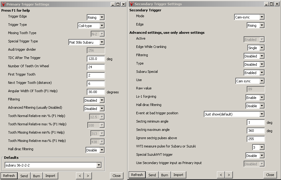
- start from a sane config, than at the bottom of primary trigger dialog click the subaru configlet (so primtrig subaru mode), than change:
- nr of tooth on wheel = 24 (yes, 2*12, not 30 !)
- tooth width = 30 degree (=3 * normal tooth)
- another_trigger_tooth=6 if 4 cyl
- (3 if 8 cyl, but assuming 4 cyl here)
- reference tooth from top to bottom: 0 18 12 6 ...
- optional: disable camsync.
- But beware: it is ment to work with camsync. Might or might not be possible to set up to operate without camsync. With COPs, use camsync as ign-dualout overloads COP ignition coils easily.
Than burn, and might need to reboot.
Please measure+figure how to set trigger tooth and TDCdelay.
(tooth 0 is after the long gap after the group of 16 normal tooth). So triggertooth=4 + 90 deg TDC-delay or triggertooth=5 + 60 deg TDC-delay SEEMS appropriate. (The strobe will tell)
Test pattern - codenamed "s362" in wav filenames and signalgenerators
Here is a [wav file] (with CamSync. Inverted to play properly. 735 RPM)
- this wav does not match the above spec
- the campulse comes in the first long gap, not the second. But it changes even within the file. The first crank rotation was good. The second crank rotation had the wrong number of teeth after the double gap. A cut and paste error.
- Note the wheels in the above photo rotate anti-clockwise since looking at the back. The drawn wheel turns clockwise. The wrong time-line in the subaru manual next to the wheel drawing was the cause of the confusion.
- So 16 pulses, gap, tooth 0, another gap, 13 pulses, gap, and it restarts
- verify any pattern (not just the first cycle), and reverse in time if necessary, also invert in audacity if needed.
- Than sectrig-triggerlog showed pulsetrain is reasonable for some testing.
- 2010-06-16 and newer VT also plays 36-2-2-2 in "Tools/Play Trigger" if s362 type is typed in the combo
- the campulse comes in the first long gap, not the second. But it changes even within the file. The first crank rotation was good. The second crank rotation had the wrong number of teeth after the double gap. A cut and paste error.
Testing - some [configs] that were used for testing
Since the 2010-06-15 experimental 1.1.76 seems to act properly (36-2-2-2 with camsync or with subaru 6+7 with camsync). Can be tried on bench or engine.
- 1.1.78 (since 2010-06-18 experimental) seems to act well on s362 (36-2-2-2 with camsync also with subaru 6+7 with camsync). Subaru code is basically same as in 1.1.76. Test on bench first, if you intend to use this. (and remember to review all the new settings like per cylinder ign-delay and fuel-pw-adjustments)
Jason's notes
- Jason can get it to trigger with camsync disabled, and can enable camsync and the rpm becomes closer, but trigg errors. If you stop stim signal it will not register rpm again with camsync enabled.
Here is a [vemscfg file] of the setup described above (trigger settings)
In Jason's engine there is the possibility of using a 4-1 cam signal. It's for the 2004 WRX STi variable cam system (disabled on this engine for now) and those sensors are still there but unused. We should figure out the 2 pulse camsync, but if the 4-1 is easier to handle quickly, I'm ok with that. There is a 4-1 on each cam, but I expect it's sufficient to just read one of the two (just like this 2 pulse cam trigger).
- from 1.1.92 VVT has special firmware support, the OLD Subaru implemetation changed,
- trigger event is the first pulse after the double missing if the cam trigger received in the tooth detect zone
- For valid measure Right sensor must connect to secondary trigger input
- Connecting the Left channel to secondary trigger input can measure as [Suzuki] trigger, needs to re-configure tdc and tooth-wheel too.
- VVT measures from the trigger cam tooth to the configured measure tooth ( default = 3 )
- Bench tested [vemslog] and [triggerlog]
Assuming that is the most retarded position. (correct ?)
link to a site, were there is crank 36-2-2-2, plus cam 4-1,
http://www.msextra.com/forums/viewtopic.php?f=131&t=36430
this is what there is on the subaru´s when the run inlet avcs, so NOT 36-2-2-2 and the 2pulse cam wheel
A triggerlog, where
- apparently B is connected (not A). B would require different config (derived from the suzuki setup), so connect A to sectrig if possible.
- also, there is an offending extra pulse !
- maybe because VR input is used with a HALL input ?
- we need to find the cause of this pulse to cure the no-sync problem (otherwise the primtrig is detected and RPM seems correct)
Camshaft-angle control
Firmware originally supported camshaft-angle control with missing tooth primary trigger. But someone on irc requested 36-2-2-2 (without writing details here or there).
We added firmware support for 36-2-2-2 (with the factory 2-pulse camsync) camshaft angle control (1.1.82), but there are still open questions...
- upto 2008 only intake cam is with avcs(vvt)
- exhaust cam is not controlled
- good, because now the special 2-pulse campattern is supported for intake cam only (only the normal 1-pulse campattern is supported for the exhaust cam).
- the max possible crankadvance is 46degrees(23degrees cam)
Engine has 2 VR + 2 cam-HALL sensors in total:
- 36-2-2-2 on crank
- 2 cam-HALL sensors(this is only tru on US model), others run VR as previus stated!!: 4-1 pattern (see pic above) on right and left inletcam, at the back of the cam (for cam position feedback)
- 2 pulse camsync (secondary vr on left camwheel)
- this is constant position, does not change when the cam PWM solenoids are actuated, right ?
- yes this was used for camsync and is constant, I believe the second trigger is a leftover from engines not running avcs,as this have also been removed from the later engines,that all run avcs,the new engines only run the cranktrigger, and the 2feedback sensores on the right and left cam
- please confirm that this is not needed when setup for camshaft-angle control (probably used as backup in the factory setup, maybe to better tolerate loss of cranksensor signal ?)
- Yep, not needed
- this is constant position, does not change when the cam PWM solenoids are actuated, right ?
Trigger inputs - 3 should be enough
- 2 onboard (primary+secondary trigger)
- and one external [DSUB9 VR to HALL] is not needed because cam sensors are HALL!
- this 3d can be connected to the 2nd cam-input, traditionally called "exhaust cam input" - even if it's not exhaust cam in this application. (and at least 1 wheelspeed is still available)
- but the special pulsetrain must be implemented for the "exhaust cam".
Output solenoids ?
- 2 solenoids (both are PWM) one on the left side and one on the right side
1/5-2012
Need help to to solve low Vr signal.
Question 1
As you can see below images of the vvt cam vr sensor is not a strong signal positive 200 mV negative 300 mV.
- actually hard to tell the DC bias. But it seems very likely that because of extremely high sensor resistance=1.9k the primtrig DC bias= 5000 * 1.9 / (1.9+18)=480 mV is too high.
- Solution is easy: use weaker pullup R30 >= 47k or higher pullup resistor instead of 18k. Even removed R30 (which is infinite Ohm) can be tried but that adversaly effects noise immunity so max 100k is preferred. (hint for a new install: order with eg. "R30=100k" in the order comment, no extra charge)
What can we try to do to make the Lm 1815 read the signal?
- adjust the DC bias (pullup) to make sure the positive peak is > +150 mV (+250 mV or higher even better), and the signal goes subzero (< -20mV at the negative peak, also important).
Question 2
This version of Subaru is not like the US made ons as shown on this side.
This Subaru is sold in Europa and Japan. It has 4 spike´s on cam distributed 90 degrees and not 3 like the US models. Also all sensors are Vr. Type (US models uses hall on cams)
- 4 pulse on cam (evenly spaced 180 crankdeg) is suitable for third trig, but NOT suitable for sectrig
- it's not a firmware question: the pattern MUST be different in the next crankrot. Absolutely required to be useful for sectrig (engine-sync)
36-2-2-2 crank, plus a 4tooth camfeedback on each cam,
This trigger setup is used on JDM and Euro 2.0 AVCS STI engines from 2001-2005 were it changes to hall cam feedback sensors with 4-1 feedback on each cam.(like the above US version)
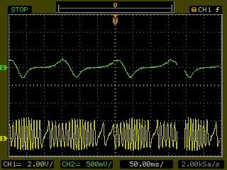
scope shot 1 : vr cranksensor 36-2-2-2 + right VR cam feedback sensor connected to secondary trigger measured with ecu pluged in
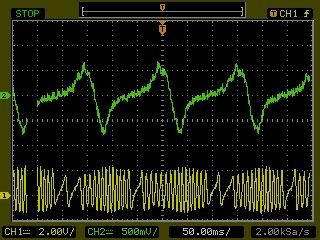
scope shot 2: VR cranksensor 36-2-2-2 + left VR cam feedback sensor connected to 3rd trigger connected by VR-Hall converter
this pic is direct from sensores without ecu connected
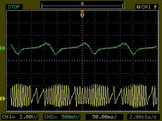
Scope shot 3: VR cranksensor 36-2-2-2 + left VR cam feedback sensor connected to 3rd trigger connected by VR-Hall converter
this pic is with ecu connected.
Not getting any output through both cam LM1815 pin12
Suggestions to get it working ?
- 3 vr sensors are all 1.9kohm
- very important: measure DC input voltage also
- primary 490mv secondary 0.1mv third 0.1mv
- how is the LM1815 pin5 set up ? ( connected to GND, connected to +5V or left open ?)
- tried with +5v and open(measurement is open)
- how do you measure output from LM1815 pin 12 ? Pulses (depend on resistor*capacitor value, but ) can be extremely short
- especially the primary trigger is set up to output very short ~44usec pulses to allow 10000 RPM * 135 tooth = 1.35 million pulses / minute for auditrigger.
- we tried with peakdetect on scope only triggerlog also only shows primarytrigger firmware 1.1.96
- especially the primary trigger is set up to output very short ~44usec pulses to allow 10000 RPM * 135 tooth = 1.35 million pulses / minute for auditrigger.