This is page is about
- a small addon board that has a AT2313 microcontroller and two LM1815 chips and some other IO circuitry.
- The primary target for the board is handling the crankwheel InputTrigger with too many (>60) teeth (pulses per crank rotation). This explains the name, but the HW is not restricted to this job.
Note that since GenBoard/VerThree v3.3 the trigger HW was modified so it can directly use the 3 input signals from the Audi wheels (2 VR crank + 1 HALL cam). However, firmware mod is still needed, and testing of course. How was the hardware modified? Is there a pin over for a hardware counter without the sacrificies needed for V3.2 (PS2 and PWM I think).
multitooth Audi crankwheels
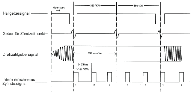
The old Five cylinder engines with electronically controlled ignition have 2 VR sensors and a hall sender. One of the VR sensors sense the starter gear (135teeth for 5cyl), the other VR sensor sense ONE pin in the flywheel located at 62deg before #1 TDC. This pin is used as a reference. The hall sender is in the distributor, and the hall trigger wheel has ONE slot acting as CAM reference. CAM ref and the Crank pin must overlap each other for the engine to start in the stock application. These engines use a homebrew ignition module with a visible TO-3 transistor in the ignition coil console. (at least the ones I have seen) Igniton computer is made by Hitachi (MAC-xx).
The small spacing between the teeth makes it impossible to synk the engine without the pin in the flywheel.
Signal timing graph from 5-cylinder MC-engine:
The same type of triggersystem is used on many older Audis, even the Audi V8 had it until it was replaced with the A8. The engines with an even number of cylinders has an 136teeth flywheel to make everything add up.
Solution:
The simplest way to do it is to intercept the signal from the 62BTDC pin after the VR interface. AND it with the hall sender signal from the distributor and pass it on to the CAM phase input on the AVR. That way you will have created a 'cam ref signal' with no slop at all.
But as I suspected Marcell said that 135teeth takes up a bit to much CPU time. It's likely that we'll make an addon board for now and add a Tiny to the mainboard later. There is even stranger trigger configurations out there.
Anyway, we use the tooth pulse after the CAM SYNK pulse direcly. Then we let every 270/5=54th (72deg in cam) signal through and so on.
Note that the ideal CAM SYNK pulse should be located around #1TDC in the compression stoke. That is not true for this configuration. With the 12453 fire order of the I5 we will have it right after #3TDC.
The PCB
First version of a small addon board (with AT2313 and two LM1815 chips) is being designed to eat signal directly from stock sensors.
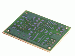
With help from CAM SYNK, it will feed suitable output signal for the mainboard. There are some unused pins available for e.g. frequency input to PWM output conversion or other purposes. Board can be adapted to work with different setups too.
make real circuit from the PCB
The PCB is very nice, but I guess we should order components together.
- let's make a BOM
- 0805 would be better in the future (so GenBoard/VerThree/RescueKit is useful)
BOM:
- C1,C2 22pF 1206
- C3,C4 100n 1206
- C5,C9 --
- C6,C10 --
- C7,C11 --
- C8,C12 --
- C13 10u electrolytic
- C15,C16 -- pwm output
- R1,R5 150K 0805
- R2,R6 5.6K 0805
- R3,R7 1.6M 0805
- R4,R8 18K 0805
- R9,R10 2.2K 0805
- R11,R12 1K 0805 (?)
- R15 -- reset pullup
- R16 -- pwm output
- R17 -- pwm output
- D1,D2,D3,D4 3v9 SOD80C zener
- IC1 AT90S2313S
- IC3,IC4 LM1815M
- Q1 4Mhz X-tal
- JP1 2x3 pin header
- JP2 2x5 pin header
Other Audi triggers:
There is also an other audi trigger arrangement on the older audis that don't have a knock sensing ignition. They only have a 5 slot trigger wheel in the distributor and no crank trigger and a hall sender controlling a auto dwell ignition module. If a few degrees of ignition inaccuracy is acceptable one of these distributors can replace the entire ignition system on the computer controlled cars.
The later models have a standard Motronic triggerwheel and a CAM synk sensor.
See also: InputTrigger
KristsMezgals - Hello Mr.Peippo!How is going with auditrigger board?Are there any updates since Nov.01 ?