The signal is taken from the Jacobs + distributor trigger.
Result of VR test
With no cap installed, and the engine still, the ECU reads many thousands of RPM (it varies) and triggers the injectors. With a 10K electrolytic cap in series it seems to read OK when triggered manually (opening the points rapidly with a screwdriver) BUT before or afterwards when stopped with ignition on, the ECU again reads many thousands of RPM and fires the injectors.
Tried it with a 22 uF BP electrolytic cap, and also with 10k to 20k of R in series. The scope shows a signal of .4V peak-to-peak, about 20ms period - this without the engine running. Sometimes it was fine and read 0 RPM with a clean waveform, but when noisy the RPM was all over the place again.
Basically, it works but there's an issue with a noisey or unstable signal, and the LM1815 is triggering at a lower than desirable voltage.
Plan A:
- Add 10K pulldown resistor to stop the Jacobs signal floating, given that there's nothing else active yet the signal is "noisy".
- Pullup would be nicer, but the Jacobs is an unknown quanity and I'd rather not break it just yet.
- why not add a 100k pullup to 5V and a 5k6 pulldown to GND ? This should stop noise, and the (appr 250mV, 5k impedance) signal cannot harm the Jacobs
- Install a 22 uF BP electrolytic cap in series after the pulldown resistor, between the trigger and the ECU, to get a -ve component to the signal.
- Jumper pin 5 to VCC at S3 to use Mode 2 on the LM1815, to avoid < 200 mV voltage triggering altogether.
- Change RC filter to 15k and 100nF to suit a V8 with 6000 rpm max, to filter any unwanted higher frequency noise.
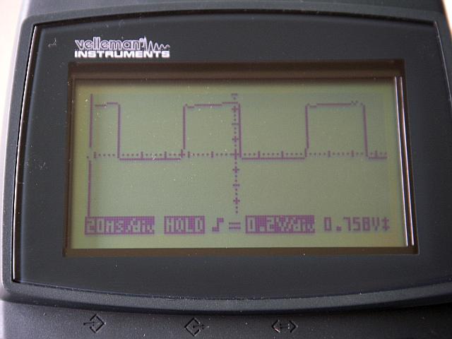
Here's the 0.76 Volt square-wave signal:
How to read this safely?
0.76V is a bit too low for a HALL setup. It might work, with some experimentation:
- try a stronger pullup and a voltage divider:
- distributor_signal (the above scopeshot) - 270 Ohm - (ECM HALL input connected here) - 1k Ohm - +5V (EC38pin28)
If this does not help (try to play with the values, eg. try several values from 680 Ohm to 4k7 instead of the 1k resistor).
Shaping the signal with active components (transistor, inverter, amplifier) is probably not justified.
VR setup
VR does not require high amplitude, but requires the signal to go under 0V. A series cap is necessary. Min 10uF 25V
- eg. the 1210 size cap in the GenBoard/VerThree/RescueKit could work
- or a bigger throughole
- or several capacitors in parallel.
- Anyone got ideas, or should I try the Hall approach instead (means soldering the ECU again :( )?
- document the history of the ECM.
- Version 3.2
- Serial
- What did you install (eg. R181 ?)
- LM1815 pin5 ? (adaptive hysteresis)
- [Photo]
- Firmware 1.0.23
- config (the simple coil-type trigger is more prone to noise than multitooth, especially with the advanced multitooth filter)
- tables
- document the history of the ECM.