Latest
Currently in the tuning and setting up stage, Simon tells me that the IAC may well be faulty as it wouldn't let the car idle below 1500-2000rpm. I am hoping to replace it with something better.
Q Faulty like? How does it behave? Maybe bad connection ? Misconfiguration ? Maybe engine just gets air from other sources that prevents lower idle RPM ? How does it react to forced mdi.. iac position ?
A With the throttle plates fully closed the engine idles high (~1700rpm), with the IAC open this takes the engine higher (2300rpm). The car's owner had a problem with getting the idle correct so he fitted a mechanical valve to restrict the air, shutting this off results in the engine stalling - which is correct behaviour and proves that there is no air getting in anywhere else. I've made a slight improvement by closing the machanical valve so that warm idle is around 1000rpm, and the open IAC RPM is around 1500.
Latest Datalog:
http://vems.hu/www.vems.co.uk/VEMSInstalls/Simon86/datalog1229.xls
http://vems.hu/www.vems.co.uk/VEMSInstalls/Simon86/datalog1228.xls
Msq:
http://vems.hu/www.vems.co.uk/VEMSInstalls/Simon86/megasquirt200512231541.msq
Config and Tables:
http://vems.hu/www.vems.co.uk/VEMSInstalls/Simon86/config.txt
http://vems.hu/www.vems.co.uk/VEMSInstalls/Simon86/tables.txt
The car:
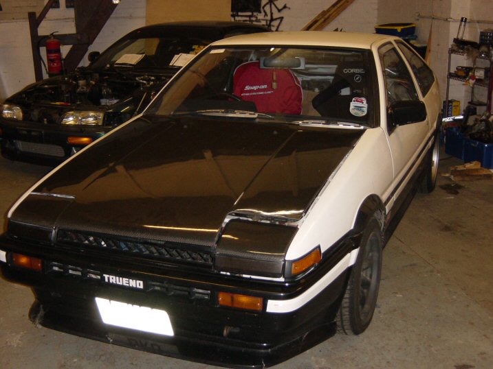
Toyota Corolla AE86
The engine:
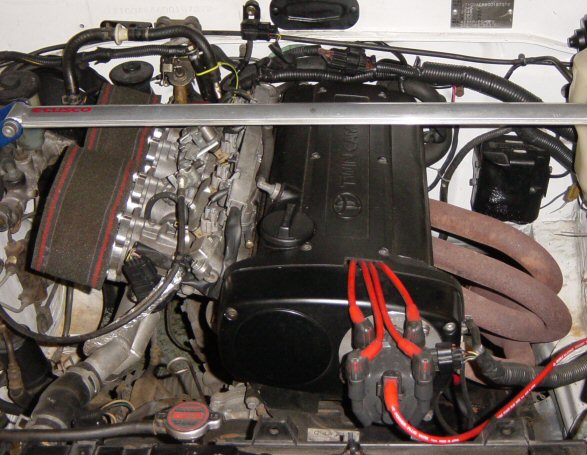
A 20V 4A series engine
The CAS:


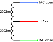
Idle Air Controller
The IAC has a two 20Ohm coils centrally fed with +12V, grounding one coil causes engine speed to drop as the IAC is closed, the other causes engine speed to rise as the IAC is opened. With no connection the IAC remains 50% open.
I think that the stepper motor controller would have to be used to control the coils.
This is implemented, and works fairly well: MembersPage/GergelyLezsak/IdleControl , but not yet merged to stable.
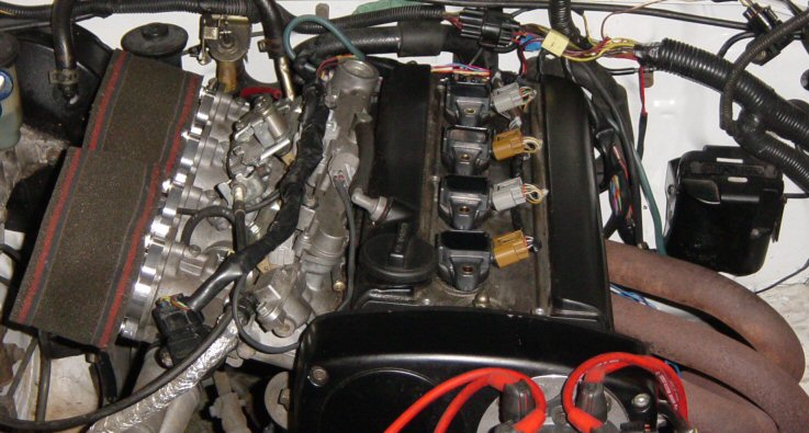
Coil On Plug
Simon would ideally like to use Toyota COPs for the installation. These plugs have a built in igniter circuit. These fit very nicely on the engine. And would make the installation look neat and professional.
We have a Toyota workshop schematic for the COP:
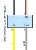
- +12V
- Ignition Fired (IGF) - signals to ECU that spark has occured
- Ignition trigger (IGT) - triggered by ECU
- Ground
Tests
Initially using two 1K resistors as a potential divider to provide a trigger voltage to IGT (measured @7V) we got a good spark.
Using a 7805 to regulate the trigger voltage to 5V.
Current through my DVM shows 13.99mA.
With a 1K resistor in the way it draws 3.xxmA but does not fire.
With a 500Ohm resistor it draws 5.56mA and sparks.
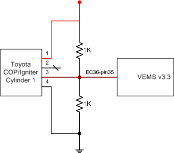
It has been suggested that the following circuit be used to enable us to keep the IGBTs and to not overload the 74HC259D.
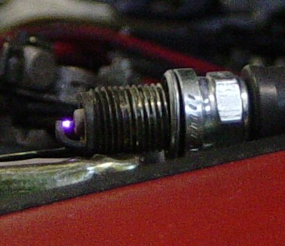
The 'test bench':
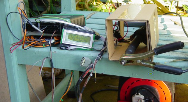
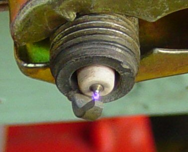
- The resulting (continuously repeating) spark with [IGT] at ~7V drawing ~7mA
- what RPM was it ? (or how many sparks/sec?) I assume the 7mA was a mean value, so we need to know frequency to calculate energy / spark
- This was read by connecting the 7V supply to the IGT pin (for a short instance? or continuously?)