vems 3.7 board
originally vr/vr setup, home-changed to vr/hall
engine BMW m50b25tu Firing order 153624 (use this order in wiring desc also)
- primary trigger=VR 60-2 crank
- R30=18k (but 10k or 27k should also work). You probably do NOT want to change anything around primtrig, since primtrig=VR already (1k would be too strong anyway)
- secondary trigger=HALL sensor on cam
- Changing to HALL should be simple, see GenBoard/Manual/InputTriggerHardWareSectrigHall
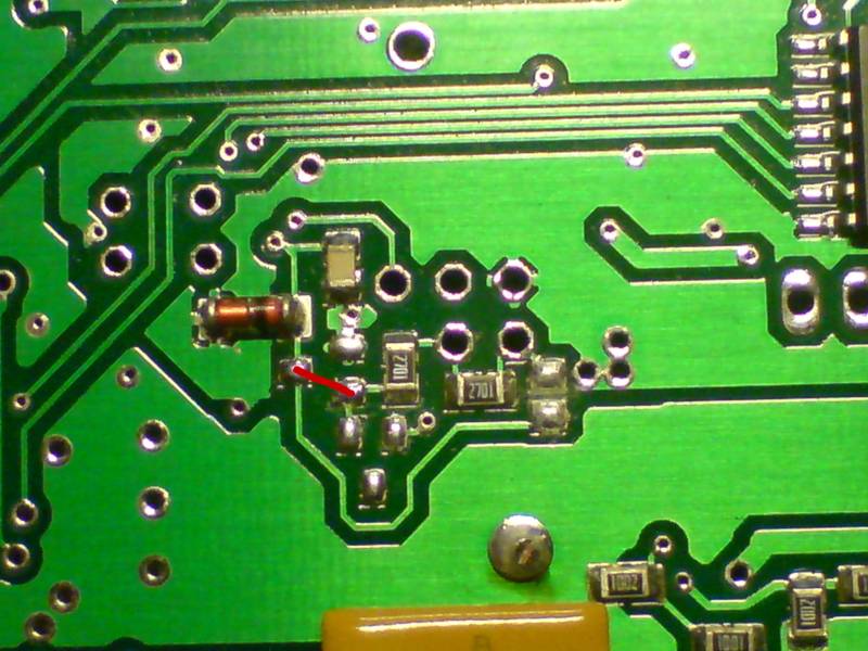
bottom view
https://drive.google.com/open?id=1eMa0XuRHrnh7cIYlCcI1ERID85F0nHxQ
top view
https://drive.google.com/open?id=1HEHAyxgnL-CFirkSctx10CqGjVuHbLED
- I understand that the sj7 which is closed need to be opened
- yes, unsolder
Also: apply the short according to small slanted line
My image looks diff at this point:
https://drive.google.com/open?id=1WQ8ZMNXJSmv1sGjeOYzjHtMW9af0N-gW
- Of course different, because yours is configured for VR
Recommended mod:
- the manually SOLDERED 2k7 (2701) resistor must be removed ( on your pic: at 4 hours from the southern end of hotmelt)
- R48 must be installed (input signal pullup: 2k7..4k7)
- some hotmelt seems to be over the most convenient place for sectrig input pullup, remove southern end of hotmelt before soldering
- soldering the removed "2701" 2k7 resistor could work if not damaged, but the rescuekit (small bag included with devices) should have new resistors
For the curious, About the other 5 holes:
- there is a red wire attached at another point on the bottom
- do i just disconnect it ?
- goes toward LM1815 pin3, should not matter. I would leave that, do the above mods, and test that way (remove if necessary, or cut+insulate or cut both ends, but it should not matter).
- actually, if you're absolutely certain the HALL sensor output is 0/5V (not 0/12V, but usually HALL output pulls to GND which is fine, even if HALL sensor is powered from 12V) the simplest hack would be to cut the northern end of red wire, blank it a few mm, and connect it to the 5V1 zener (SOD-80, left on your pic) stripe-marked cathode (or SMD pad under the cathode; trace goes to processor pin). "2701" should stay in this case (act as a pullup resistor, even if not originally ment as input pullup)
- This hack bypasses input protection so not normally done: the above recommended mod is better if possible (you have an SMD or throughole resistor 2k7 .. 4k7)
First input tests:
- input disconnected: DC voltage measured >3.7V
- 1k between input and GND (instead of HALL sensor), DC voltage should measure: between 0.5V and 1.5V
Than verify in InputTrigger/TriggerLog
done as per pic
moved the resistor so it looks as above
connected the red line in the above pic
got 5 v at signal and verified it by putting 1k resistor between signal and supply and got 1.5 v
thank you
done the wiring, connected the pc using a usb ftdi cable, updated the ini files on the software then i have done the wiring according to the vanos in
http://vems.hu/download/v3/Motronic88/325-M50-vanos-and-nonvanos_OBSOLETE.xls
and used
http://vems.hu/download/v3/Motronic88/base_M50_vanos_1.2.31.vemscfg
the car is a 92 m50 i imagine it has vr primary sensor
which according to above pic my ecu is vr primary
(how do i know which one on crank sensor is signal ? middle or end one)
on the primary trigger there is 3 pins 3 wires
i have connected the yellow wire to ec36-27(thats the only sensor connected) and connected the black to ec36-5 close to ecu and shield to battery ground. when i power on just ecu to record trigger log it says NO INPUT connected
Crank sensor reads .519 KOhms across signal and ground
- sounds good (although "it is working" can be confirmed with scope, or soundcard, or signal input to VEMS).
- ec36-27 is input (not output), measures DC voltage=2.84V (make sure to be very clear about what is measured, where, how)
- 2.84V is way too high for primtrig VR, We'd expect around: 5 * 519 / (18519) = 0.14 V DC voltage at EC36/pin27
- My ecu has 183 resistor at r30
- R30=18k is good, but still some strong pullup is in effect around primtrig VR input.
EC36-28 not used (no wire in ec36/28)
Should i add wire be joining ec36-28(5v out) to 27k then to the crank signal wire yellow
- the crank signal is VR, which does NOT need strong pullup (actually, your R30=18k seems good, but the voltage indicates something weird, maybe unintentionally tinkered around primtrig that was factory VR in the first place ?)
Why not setup sectrig properly?
- m50b25tu engine has camshaft angle control, it is ugly to run such a nice engine without sectrig (and finally VANOS)
- you would also find out if, for some reason sectrig HALL works, but primtrig VR not
Maybe p259 damaged by insufficient ground ? That could be one possible reason to have no LM1815 (+5V) supply internally (can you measure ?), and no primtrig VR reading.
- of course VR signal scopeshot, or at least DVM AC voltage measurements could help a lot to diagnose.
If the ecu is powered up and grounded the ec36-27 is showing 2.84V between ec36-27 and ground with no sensor plugged in !
- Can be OK
- Doesnt the vr need 5V?
- no, this measurement is not very indicative. Measure with VR sensor (or other KNOWN, documented resistance) connected between EC36/27 and GND
I understand its input but its got 2.84V comingout of it thats why above I actually meant to add pin28 to pin 27 to get the 5V via 27k resistor
- measure with VR sensor connected
I do not have a scope to read the sensor.
Cld i have a image of where to check for voltage as uve mentioned above and which pinon the lm1815
- checked the 2 lm1815 both have 5V at pin 8
- that is VERY good news, thanks for checking.
I will be running the sectrigger too but wanted to get the primary working first
I measured the vr input close to ecu at pin27 and battery ground with the sensor plugged in it read 0.138.(confirmed test)
when i open the record trigger with the tools drop down it says no trigger in the bottom corner. and doesn't make a difference if i plug or unplug it.
i have turned the cranked the engine 1-2 turns it still has no difference.
realised that even if it is plugged in it says no input trigger till u crank it for longer (only needed if sectrig is not installed, or disabled)
ok cranked it for a bit longer and finally got a signal
looking at the trigger log i realised i was getting (missingtooth=1 cycle58)
realised the poarity need to be swapped as in black wire to ecu and yellow wire to ground near ecu
finally got missing tooth=2cycle58
after a few tries i managed to get a nice log
https://drive.google.com/open?id=1Sc8Zl_yDUyR2saVEYHr7X-nRdf3jjjt8 (old firmware 1.2.0)
could you confirm if the cylinder and injector coding in the m50 vanos basemap is correct as i feel its wrong
http://vems.hu/download/v3/Motronic88/325-M50-vanos-and-nonvanos_OBSOLETE.xls
this is my last config if you could check triggersetting for a m50b25tu single vanos and the injector visual as its a bit confusing i have it as in the ecu according the above excel sheet
ie
Inj outputs
cyl1 inj going to pin 20
cyl5 pin 7
cyl3 pin 9
cyl6 injector to pin 8
cyl2 pin 18
cyl4 pin 19
IGN outputs
cyl 1 coil pin 12
cyl 5 pin 35
cyl 3 pin 36
cyl 6 pin 11
cyl 2 pin 33
cyl 4 pin 34
Fpump pin 31
Please update this page: correct, exact format, like EC36/31, and make logical channel number like "ignch N" appear
uploaded the 1.2.31 firmware restarted and validated the m50 vanos map with the inj and coil changes as its different to the excel doc
my trigger log
https://drive.google.com/open?id=1NYTYx-d9BLSVdkv-mty9lr5N8x1_1inj
my config file (new firmware)
https://drive.google.com/open?id=15mR1q_rnBNq_9ybcPSn_w76O9AV2ZatF
does not fire ?
Please note that there is a working [M50 Vanos base config] under [downloads] (with a quite sane pinout)
- of course the outputs must be adjusted to match if the pinout deviates
Hello Optimap,
I have reviewed your config and triggerlog (fw1.2.31.triggerlog and newfwvanosmafppin31and corrected to firing order.vemscfg).
From my review there should be no configuration problems prohibiting you from starting the engine; Have you verified the ignition timing in cranking (INJ fuse removed) so ING only) on all cylinders before attempting to start the engine ? If so you should be good to go.
If your fireup problem persists, please supply a vemslog of engine cranking 8-10 seconds (but not firing) so i can review your case using both configuration and ecu realtime variables. We'll work from there.
Best regards, Dave
____________________________________
i have used
http://vems.hu/download/v3/Motronic88/325-M50-vanos-and-nonvanos_OBSOLETE.xls
this wiring contradicts the vanos map provided. unless i am doing something else
so injector wiring
ec36-20(inj4/injector Dch 08)connected to injector cylinder 1
ec36-18(inj6/injector Fch 32)connected to injector cylinder 2
ec36-09(inj5/injector Ech 16)connected to injector cylinder 3
ec36-19(inj2/injector Bch 02)connected to injector cylinder 4
ec36-07(inj1/injector Ach 01)connected to injector cylinder 5
ec36-08(inj4/injector Cch 04)connected to injector cylinder 6
the m50 vanos map [M50 Vanos base config]has the pins different to the excel sheet provided
if i test the corresponding pins they fire the right cylinders (coil pack disconnected and the rail moved safely away from inlet)
coil pack wiring
ec36-35(ignition output 0) connected to cylinder 1
ec36-34(ignition output 2) connected to cylinder 2
ec36-11(ignition output 4) connected to cylinder 3
ec36-12(ignition output 5) connected to cylinder 4
ec36-36(ignition output 3) connected to cylinder 5
ec36-33(ignition output 1) connected to cylinder 6
my config
https://drive.google.com/open?id=1B6gF1RtzKk8Cy73gr1bN6641eCkVwHyU
my trigger log
https://drive.google.com/open?id=1fi9NhIWwUhP3QASejhoyD3hefjQlKB5V
my vems log
https://drive.google.com/open?id=13-oY_0DnrBEdOlJ6fjvwFC8-0bH545Ij
tps has been caliberated connected and the 2 triggers are connected.
lambda and iac vaccum to ecu is not connected
if i test the injectors i can see fuel coming out as in if the left side says 1 then cylinder 1 inj fires with test on and goes off but during cranking i dont see fuel on cranking (tried this with coils disconnected obviously)
Hello Optimap,
I have reviewed your vemslog (v3.3_u004637-2018.04.17-17.54.44.vemslog).
From my review your map sensor is not calibrated properly, it is showing 136 kpa while being in ambient air, this most likely means you have a 300kpa map sensor mounted; not 400 kpa as calibrated; update your ecu calibrations accordingly.
You are not getting any fuel because overboost fuelcut is active (see pulsewidth gauge and calc model).
However before any thing else Have you verified the ignition timing in cranking (INJ fuse removed) so ING only) on all cylinders before attempting to start the engine ??
No further review of configuration until basic directions are followed and questions answered.
Best regards, Dave
hi thanks for getting back
the engine was timed and running on the original ecu so the engine has been timed with the right tools
i might sound ignorant but not sure what you mean by verify ignition timing my timing gun dont work with coils ?
if i go to the test function
and test the 1st cylinder injector it fires no 1
then the next one in firing order it fires the injector on cylinder 5 and so on ..
the excel document and the base map have different pinout could you check so i know my wiring is correct.If u say that the base map is correct to the excel sheet them i will load the m50 vanos1.2.31-13xxx and use it but it is different so i am getting confused
the base map m50vanos 1.2.31-13xx has
ec36-17 as cylinder 1
ec36-6 as cylinder 4
where as in the excel doc they are idle control pins
the others are also different
please advice
i have caliberated the map it was a 250 sensor i am now getting fuel
also my tdc angle for cylinder 1 is 324degree
but the base map is set different
(i am a noob at this sorry )
thanks DEV