New:
- ECU (still) resetting causing big hesitations in engine
http://www.vems.hu/files/KevinBlack/Cg%20Drive%201.xls
- customer reports that the tach "jumps up" when the hesitations occur
Please post uptodate config dump so it can be examined for output-collisions or other potential configuration problem.
I think after harness tests we should send you replacement ECU to see if it behaves (should also be tried with same config).
The config dump is extremely important, the first step of the procedure.
If the replacement ECU fixes it we'll have to dump config from that too and compare to find out.
- '''Thanks, the config dump was linked below, here it is:
- OLD dumps below - secondary trigger was "disabled" in MT(fixed)
11/19/08
- stuck in bootloader modeSOLVED, edited "upload-firmware.bat" and used PSI Tuner to reload the firmware
- USB-Serial adapter (of course)
- We are using the newest VEMSTune 10-20, and uploaded firmware 1.1.27, along with PTC 2460_425 and 2063_256 files.
- The firmware started to upload and then stopped, and displayed error windows about the bootloader mode or whatever. Now the ecu wont connect in MT or VEMSTune.
- I had him bridge serial port 2-3 with the ECU OFF, then turn the ECU ON, did this a few times. (not needed if it starts in bootloader anyway. Wont hurt either)
- We tried turning the ECU OFF (before uploading again) after bridging the pins, was this wrong?
- no problem at all
- I cant get anything to work now. Any ideas?
- try with megaloader (see the batch file in the MegaTune releases) or prog.pl
- we didn't experience that in the lab, but occasionally hearing about similar cases. Autronic manual states that you have to disable buffers (emil_ a friend of mine tried 3 different usb-rs232 and still fails). Disable buffers in device manager, find the port, properties, port settings, advanced
11/18/08 - Engine is running. I had to rotate the ignition outputs.
NEW Order: h[2]=10 76 60 30 20 50 50 50
'''In MT = 2-3-6-7-1 (bottom to top)
OLD Order: h[2]=76 60 30 20 10 50 50 50
'''In MT = 1-2-3-6-7 (bottom to top)
'''I assume this is because of the secondary trigger placement.
Can someone check the rest of the config to make sure it is correct for a 3B engine?'''
OLD dumps below - secondary trigger was "disabled" in MT(fixed)
http://www.vems.hu/files/KevinBlack/CGFinalBaseDump.rtf
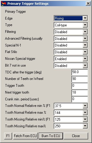
Primary Trigger Settings, note no "crankminper" setting, does this explain the trigger error? (should be ~2600 for 8000+100 rpm limit)
- What about the "Nissan Trigger enabled?
Ignition Configuration / Wiring, 5 IGBT Outputs
IGN Output - EC36 - Color - Cylinder
10 - 33 - Blue(Tape) - Cyl 1
20 - 34 - Black - Cyl 2
30 - 36 - Brown - Cyl 4
60 - 24 - Red - Cyl 5
70 - 10 - Blue - Cyl 3
Firing Order 1-2-4-5-3
Car Information:
- 1991 Audi 200 20vtq,(3B)
- Stock injectors, 3.5 bar fuel pressure
- 5 individual 12V power coils
ECU information
- Webshop assembled Serial # 2016
- 1.1.27 Firmware
- Marcell config and tables for 3B
- Megatune 1.1.23 and or V3GUI for tuning
Questions:
- Does 3B Engine need crankhome wires reversed?
- yes
- Done - Black crank-home connector Pin1=Red to ECU 48, Pin 2=Violet to ECU 49
- yes
- What is Cam Hall inversion?
- a small (NPN) inverter inside the box makes low/hi from hi/low input (on EC36/13)
- Need to check config (Marcells config shows 90 tooth for trigger? I thought it is 135 tooth?)
- actually 270 tooth, so 90 because of the divby3
- Need to verify all trigger functions - shipping this ecu to a customer
- you can use soundcard, left channel to EC36/27, right channel to EC18/12. Use c270 trigger
- Need documentation about how P259, INJ, etc. is wired to Motronic55 connector
- See the 3B column in the spreadsheet. http://vems.hu/download/v3/Motronic55/motronic-AAN-ECxx.xls
- also see the functions in the config. Eg p259/0 (ec36/4) is tach out.
- also keep track of what you ordered. The SSC6 pinout can vary according to customer request (pins can be analog input, or ignout logiclevel/power ign out, or gnd)
Requested Configuration
MAP connection 400kPa onboard - brass nipple
Flyback - 30v Diode
LCD - Connector through endplate (DSUB9 on endplate or flying loom)
EGT - Flying Loom through endplate
Knock - Via Motronic55 Pins
IAT - Audi PTC Sensor (430 Ohm pull-up)
Ignition Configuration, 5 IGBT Outputs
IGN Output - EC36 - Color - Cylinder
10 - 33 - Blue(Tape) - Cyl 1
20 - 34 - Black - Cyl 2
30 - 36 - Brown - Cyl 4
60 - 24 - Red - Cyl 5
70 - 10 - Blue - Cyl 3
Firing Order 1-2-4-5-3
2 Analog Inputs, custom connector
- Red (Analog 7) 8,400 Ohms to Pin 12 5V
- Blue(Analog 6) 8,400 Ohms to Pin 12 5V
Launch Control and Shift Cut Setup
- How do I wire and set-up the Launch/Shift as described below?
As you see, the "AAN ECU extra connector pins" has 3 analog inputs, we use one brake-light switch mounted under clutch (and a series switch that can disable it) to pull down (activate) the (shared) input for shiftcut and launch.
When activated with TPS < iac_tps_threshold launch is activated (TPS can be pressed after activation). Otherwise shiftcut is activated.
WBO2 Configuration
SSC Pin - Flying Lead - WB02 Pin
- 1,black Nernst,WBO2 Pin 1
- 2,White +12V (motronic pin27) 3
- 3,Grey Heater(-),WBO2 Pin 4
- 4,transparent Pump(-),WBO2 Pin 5
- 5,thin red Pump(+),WBO2 Pin 6
Suggestion - make WBO2 wire colors match the LSU4.2 sensor
SSC - Color - WBO2 Pin
- 1 - Black - 1
- 2 - Grey - 3
- 3 - White - 4
- 4 - Yellow - 5
- 5 - Red - 6
General Audi Information
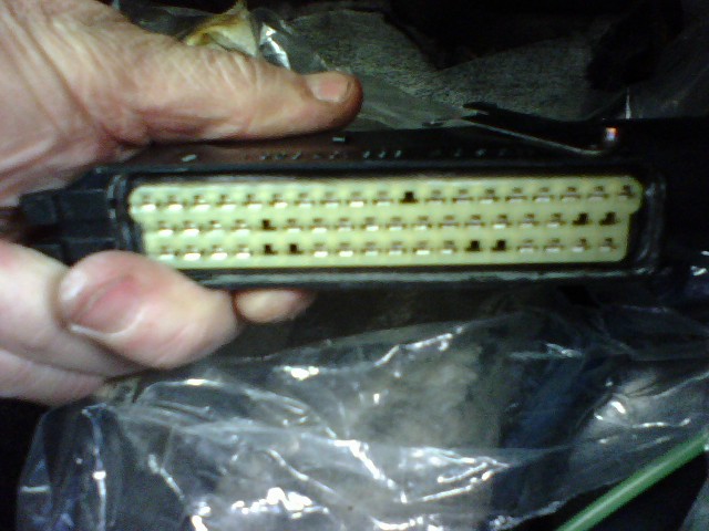
Pic of ECU Connector:
3B Wiring Pinout:
http://www.s2central.net/motronic_pinout_3B.html
3B Wiring Schematic:

Audi 3B Information:
http://www.s2central.net/motronic_02.html
http://www.sjmautotechnik.com/trouble_shooting/20vboost.html