Inline 5-cylinder, sequential ignition with camsync
Primary trigger: 60-2 w/ VR sensor.
Secondary trigger: Single tooth w/ Hall sensor.
The rising edge of the cam wheel hits the sensor after cylinder three fires and before cylinder one does.
Firing order is 1-2-4-5-3.
MembersPage/RonnieH has set up VEMS on a very similar motor also with seq. COP. After some additional reading, his settings seem obsolete due to code changes.
Primary trigger settings
| Field name | Variable name | Value [decimal] (Value [hex]) | Comment |
| Primary Trigger | primary_trigger | 1 (0x01) | For multi-tooth trigger without filtering (I think). 0x09 is with filtering? Which should I use? |
| Edge | Rising | ||
| Type | Multitooth | ||
| Filtering...Bit7 | Disable | ||
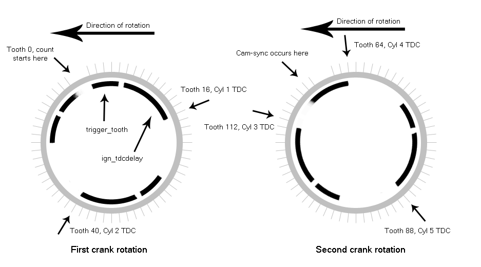
| TDC after the trigger | ign_tdcdelay | 60 (0x3C) | The GenBoard needs to know ahead of time when a cylinder is going to be at TDC. This is to allow for a certain amount of ignition advance. It needs about 60 degrees of 'lead time'. ign_tdcdelay is this lead time. Look at the tooth under the sensor at TDC of cylinder one (16 in my case), count backwards toward the missing teeth until you are ~60 degrees BTDC. In my case this is exactly 10 teeth and 60 degrees. |
| Number of teeth on wheel | tooth_wheel | 58 (0x3A) | 60 "total teeth" - 2 missing teeth = 58 actual teeth |
| Trigger tooth | trigger_tooth | 5 (0x05) | TDC of cylinder 1 (tooth 16) occurs 15 teeth after the first actual tooth following the missing teeth. 15 teeth is 90 degrees. ign_tdcdelay is already 60 degrees, leaving 30 degrees (or 5 teeth). This is trigger_tooth. Confusing as shit, I know. See illustration below. More concise explanation here: InputTrigger/MultitoothTriggerWheel |
| Next trigger tooth | another_trigger_tooth | 24 (0x18) | (from GenBoard/UnderDevelopment/FirmWare/TriggerRelated, 60 (teeth on the wheel) * 2 (wheel revolutions per cycle) / 5 (ignition events) = 24 teeth between events |
| Crank min. period | crank_minper | 188 (0xBC) | 60 (seconds) / 8000 (max rpm) / 5 (number of engine events) * 2 = 0.003 (seconds) = 3000 (microseconds). In units of 16usec, so 3000usec / 16 = 188 [decimal] = BC [hex]. Can someone confirm this is the correct formula? Or even what this value means? |
| Tooth normal relative min % | 25% | ||
| Tooth normal relative max % | 150% | ||
| Tooth missing relative min % | 200% | ||
| Tooth missing relative max % | 413% |
Some of this mess stated differently: The way I understand it is when VEMS sees a missing tooth it says "Ok, how many teeth do I need to count before I'm [ign_tdcdelay] (60 in my case) degrees BTDC? I'll count [trigger_tooth] number of teeth." So in this case it counts 5 teeth, at which point it knows it's got another 60 degrees to go before the next cylinder is at TDC on the compression stroke.
It can then find the next tooth to start counting off at by doing something like this:
[next_tooth_to_count_from] = ([current_tdc_tooth] + [another_trigger_tooth]) - ([trigger_tooth] + [ign_tdcdelay] (in teeth, not degrees))
In our case, for the second ignition event:
[next_tooth_to_count_from] = (16 + 24) - (5 + 10 (60 degrees in teeth)) = 25
This matches with what is on the diagram posted below.
Note: This is probably not even close to how the wheel decoder in VEMS actually works, but for my purposes it makes everything infinitely simpler to grasp.
Secondary trigger settings (these are not used in 1.1.x, so only here for future use)
| Field name | Variable name | Value [decimal] (Value [hex]) | Comment |
| secondary_trigger | (0xFE) | For rising edge trigger | |
| tooth_wheel_twidth1 | 24 (0x18) | Width of a single tooth on wheel, in quarter degrees (360/60 = 6 degrees per tooth, 6*4 = 24 quarter degrees per tooth, 24dec = 18hex) | |
| tooth_wheel_twidth2 | 0 (0x00) | Not sure on this one either, changelog says set this to 0, but why? | |
| Rising Edge | cam_sync_r_edge_phase | 2 | See: Note |
| Falling Edge | cam_sync_f_edge_phase | 6 | See: Note |
| Engine phase, when to reset | reset_engphase_after | (0xF0) | See: Note |
Note: According to GenBoard/Manual/InputTriggerCamSync
Re-iteration for this section: The rising edge of the cam wheel hits the sensor after cylinder three fires and before cylinder one does.
Firing order is 1-2-4-5-3.
Ign. outputs will connect as follows (for 2+6 configuration, according to PhatBob's User Guide):
| Cylinder | Ign. channel | ECU Pin |
| 1 | 00 | EC36/35 |
| 2 | 10 | EC36/33 |
| 3 | 40 | EC36/11 |
| 4 | 50 | EC36/12 |
| 5 | 60 | EC36/24 |
h[2] is ignchannel array, h[2] = 00 40 60 50 10 00 00 00. So the array is traversed backwards starting at '10' (cyl. 2) (since "Ignition outputs to use in h[2]" will be '04..00'). Because the ignchannel traversal is reset after the ignition event following the cam-sync, cylinder one needs to fire last in the order.
Differently stated: h[2] = 00 <cam sync occurs here> 40 60 50 10 <traversal begins here> 00 00 00
I drew a pretty picture:
According to the changelog for 1.1.x: h[1] is the reference tooth array (trigger_tooth and ign_tdcdelay is added to this to get TDC), for each output specified in respective h[2] entry.
h[1] = 01 61 49 31 19 00 00 00 (Note: These numbers are in hex)
Stated in decimal, h[1] = 01 97 73 49 25 00 00 00
Confirmation on the above values would be greatly appreciated.
h[1] (more commonly known as trigger reference tooth table) should be a multiple of "Next trigger tooth" and always start with 0, so 0,96,72,48,24 would be correct. You'll have to re-zero your timing after this correction.