Ignition parameters for odd fire coil type configuration.
As I understand, the Marelli microplex logic for starting the ignition is:
| On CamTooth 1 | START COUNT Crank teeth |
| On CamTooth 2 | If CrankCount=2 then START IGNITION, (next cyl. is c2 90° from here |
In software they simply made a switch for the 12 cases
given by the 12 teeth met in a 720° cycle. Also they simply put a
constant 120° dwell time since there is always 120° (that is 30°+90° or 90°+30°)between the 2 previous teeth and the firing tooth. See here after
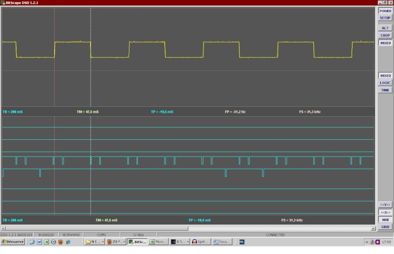
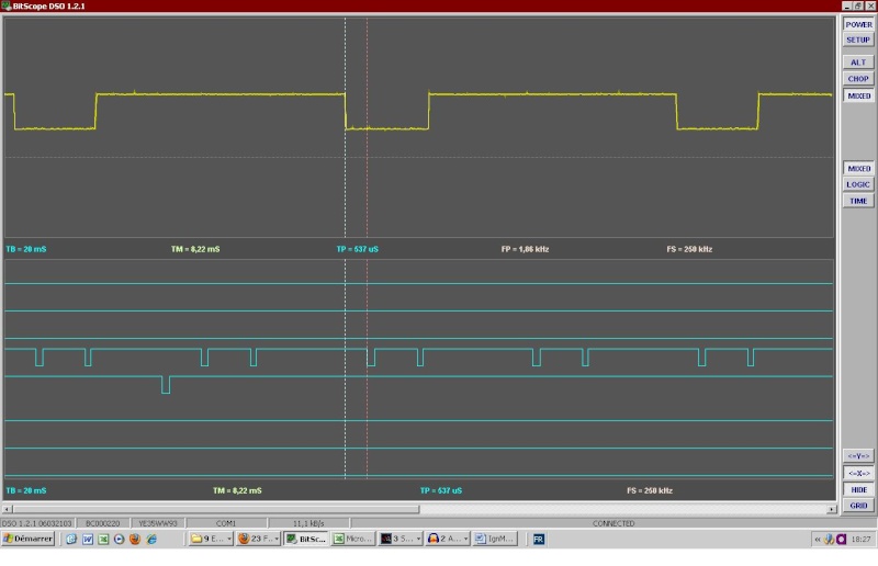
BLEU : IgnitBiturbo1000.wav - JAUNE: IgnA - VERT IgnB
Question
Lets note the 6 tuples of 2 crank teeth which are seen by the VR sensor during a double revolution of 720 ° by the following:
/t01/.30°./t02/ .. 90°.. /t03/.30°./t04/ .. 90°.. /t05/.30°./t06/ 90°
/t11/.30°./t12/ .. 90°.. /t13/30°/t14/ .. 90°.. /t15/.30°./t16/ 90°
Indeed cylinder numbering is not useful at this bench test stage. Although things are more involved we just want to exercise the VemsTune capabilities as a first attempt and observe with a scope what's coming out.
So lets us ask Genboard to fire 10° before the following teeth
/t01/ ..... 150° .... /t04/ .. 90°.. /t05/ ..... 150° ....
/t12/ .. 90°.. /t13/ ..... 150° .... /t16/ .. 90°..
What are the options to set from the VemsTune menus?
Answer
- download the config from MembersPage/OddFireSixCyl
- dragndrop file to relevant dialogs ("primary trigger", "reftooth table"). This is the quick way to import the displayed settings (changed entries change to red)
- the ign outputs must be set to your ignout wiring
Can we do odd firing with coil type triggers? How?
The config used the individual cylinder spark delay.
Anyway I don't even know on which crank tooth Firmware 1.1.90 start counting. I should make a triggerlog next time.
As for the use of spark delay, I think I have understood :
Because of the odd fire configuration of genboard, it remains 6 reference trigger pulse per double cycle from the 12 crank triggers, hence they are 120 ° apart. That is
/t01/. 120°.. /t03/.120°.. /t05/.. 120°
/t11/..120° /t13/ ..120° /t15/..120°
or
/t02/. 120°.. /t04/.120° etc depending of when firmware does the sync from the cam trigger (I have to find out that)
Now if the it is fire on the reference triggers AND for each of them 30° in delay (say d0i etc) as well and on a separate output, we get 12 firings which are :
/t01/.30°./d01/.90°./t03/30°/d03/.90°./t05/.30°/d05/. 90°.
/t11/.30°./d11/.90°./t13/30°/d13/.90°./t15/.30°/d15/. 90°.
and from these 12 firings we can use 6 which are as searched:
.30°./d01/.90°./t03/.150°/d05/. 90°.
/t11/.150°/d13/.90°./t15/.120°.
Question
Is this the trick?
How do we set the delay parameters and configure for 12 firing events?
Help for ignout config
So that we can help with ignout config that matches your wiring, fill this in:
- What is the exact position of the 2 primtrig pulses coming after the second sectrig pulse ?
- What is the cylinder that follows ?
- which ignout is that connected to ?
- than list the remaining (5) cyl / ignout entries
- always mark the angle separation between the cyl/ignout entries (in a separate line, to be clear, 150 or 90 degrees)
Answer
I am not at this point. Next step is to get on test bench the 6 firings events with proper phases : 90-150-90-150-90-150 whatever the ignout.
As I said I have not yet found the delay parameter.
After this step completed, I would connect the firings lines (with diodes) for the bank A all together, do the same for bank B and run the engine with the distributor the same way it is done with the Microplex (we are still far from there).
Inj outputs - same order as ign
Use the same injout entry as the ign (if topmost ign is, say, cyl3, topmost inj should be also cyl3 output for unbiased inj-angle positions).