Ignition parameters for odd fire coil type configuration.
In the descriptions, let's always use the teeth after the short gap ( short gap=30 deg, not the long 90 deg gap) as a reference,
- either 1 certain tooth (marked with DOUBLE red dot on pic below) as a reference for all TDC
- like: 10crankdegBTDC (cranking sparkadv) points are (ASSUMED - to be confirmed or corrected) 90, 240, 330, 480, 570, 720 degrees
- or the last such tooth (marked with red dot on pic below). This, by itself does not cause a confusion since the tooth after shortgap are evenly spaced every 120 degrees (so it's just "mod 120" deg of above values)
- like: 10crankdegBTDC (cranking sparkadv) points are (ASSUMED - to be confirmed or corrected) 90, 0, 90, 0, 90, 0 degrees
Yes 10° before TDC is confirmed by the manual when adjusting the VR sensor position, and the eprom code it self since 10° is subtracted from the ignition map value to make a refence for teeth pulse.
Indeed on can start counting from the crank teeth after the short gap which follows the cam tooth after the short cam gap (double dot on the pic).
However if one does not that the first cylinder to fire is with the 30° delay it should be better that the fist fire comes for the first tooth of the short gap so that the next firing commes at 120° +30°delay which is in phase with the 2nd tooth of the next short gap (yes after the long gap !!).
For Microplex everything seems more simple, see below.
The first achievement I would reach is
- get VEMS firing for bankA and for Bank B the same way that it is done by the biturbo Ecu. Remember firing for bankA is related to the first crank teeth of short gap and bankB for the second - or the reverse, it does not matter. Then, since the firing on each bank are evenly timed, it would just remain a matter of wiring the thing properly.
- have this firing robust with regards to noise or errors (robustness and tests are to be defined)
All non-conforming descriptions should be changed or deleted. Any misunderstanding can result in problems and lots of wasted time for all involved.
As I understand from the eprom code, the Marelli microplex logic for starting the ignition is the following
| Event | Do |
| On First CamTooth read | Start Count Crank teeth |
| On Second CamTooth read | IF CrankCount = 2 Do next cycle Ignition ELSE wait for CamTooth |
Indeed it is even more robust than that since there is a switch case for the 12 crank teeth of an ignition cycle and the 2 Cam teeth are expected the first before the 11th and the other after the 12th.
Besides they simply put a constant 120° dwell time
- (but this is too long at low RPM)
Cyl2 TDC is 100 degrees from that Crankcount=2 pulse.
- Humm, the Crankcount=2 pulse is 120° before what we have called tooth 1 or 130° before the cylinder relevant to that tooth( we may call it Cylinder 1)
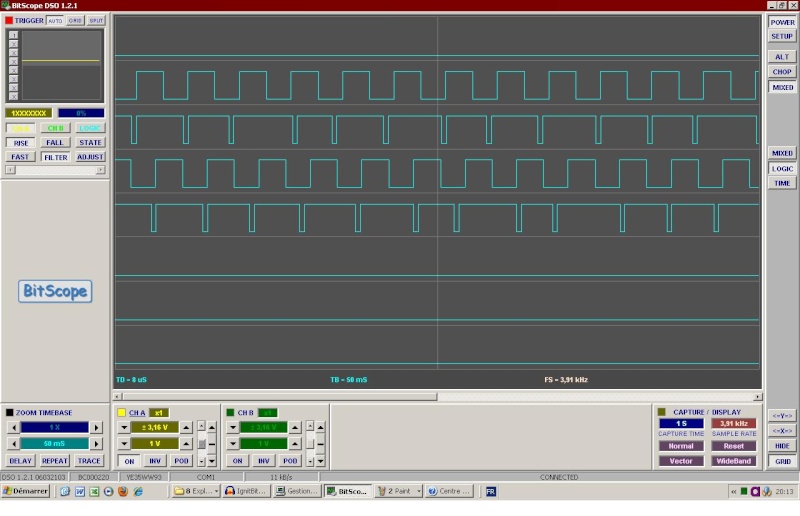
BLEU : IgnitBiturbo1000.wav - JAUNE: IgnA - VERT IgnB
Lets note the 6 tuples of 2 crank teeth which are seen by the VR sensor during a double revolution of 720 ° by the following:
/t01/.30°./t02/ .. 90°.. /t03/.30°./t04/ .. 90°.. /t05/.30°./t06/ 90°
/t11/.30°./t12/ .. 90°.. /t13/30°/t14/ .. 90°.. /t15/.30°./t16/ 90°
Genboard has to fire 10° before the following teeth
/t01/ ..... 150° .... /t04/ .. 90°.. /t05/ ..... 150° ....
/t12/ .. 90°.. /t13/ ..... 150° .... /t16/ .. 90°..
Can we do odd firing with coil type triggers?
Answer
- so download the config above, or from MembersPage/OddFireSixCyl
- dragndrop file to relevant dialogs ("primary trigger", "reftooth table"). This is the quick way to import the displayed settings (changed entries change to red)
- the ign outputs must be set to your ignout wiring
- the triggerlog also shows the spark events, so examine that too (and use the strobelight) before actually trying to start the engine
- yes, the showed configs used the individual cylinder spark delay 0,30,0,30,0,30 to make 90,150,90,150,90,150 "odd-fire" sequence from the even 120,120,... sequence.
Anyway I don't even know on which crank tooth Firmware 1.1.90 start counting. I should make a triggerlog next time.
As for the use of spark delay, I think I have understood :
Because of the odd fire configuration of genboard, it remains 6 reference trigger pulse per double cycle from the 12 crank triggers, hence they are 120 ° apart. That is
/t01/. 120°.. /t03/.120°.. /t05/.. 120°
/t11/..120° /t13/ ..120° /t15/..120°
or
/t02/. 120°.. /t04/.120° etc depending of when firmware does the sync from the cam trigger (I have to find out that)
Indeed if we note d03,d11, d15 the ignition events delayed by 30°, we get what we need:
/t01/.150°. /d03/.90°./t05/. 150°. /d11/.90°./t13/.150°/d15/. 90°.
Help for ignout config
So that we can help with ignout config that matches your wiring, fill this in:
- What is the exact position of the 2 primtrig pulses coming after the second sectrig pulse ?
- What is the cylinder that follows ?
- which ignout is that connected to ?
- than list the remaining (5) cyl / ignout entries
- always mark the angle separation between the cyl/ignout entries (in a separate line, to be clear, 150 or 90 degrees)
Answer
I am not yet at this point. I would connect the firings lines (with diodes)* for the bank A all together, do the same for bank B and fire the engine through the distributor the same way it is done with the Microplex (we are still far from there).
I finally understood that this is useless since it is possible to drive freely any ignition event to any ignition output of the genboard (yes Versatility)!! and this is already done by the config file since
h[2]=70 40 70 40 70 40 70 70
As we see only 2 output ports are used in order to fire the cylinders of bankA or bank B.
Of course now one needs to know which is which and the Triggerlog which now records the ignitions events would be of great help for that.
I also found out the delay parameters from the VemsTune menus "Cyl separated Spark delay" and was surprised to see it is already set as one wanted, this is also define, I presume, by the table h[3] of the config file (MembersPage/OddFireSixCyl):
h[3]=00 78 00 78 00 78 00 00
because 0x78 = 120 = 4*30°.
First Bench tests
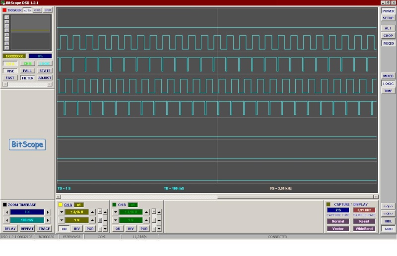
- Here after some bench test from the board ...
- Bench tested scope shot showing the requested timing:
- ch1 : secondary trigger
- ch2 : primary trigger
- ch3 : ignition output ( all slots set to same output in this test )
- Full [here]. Change the following:
- we used same ignition output in all 6 slots to make it easier to scope (use 6 different outputs in real life, that drives the 6 transformers)
- set ign TDC delay (apparently lower than 40 degree also seemed to work, even during cranking)
- swap the 0,30,0,30,0,30 in the "individual spark delay" table to 30,0,30,0,30,0 if necessary
- Then mine ...
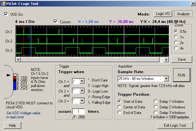
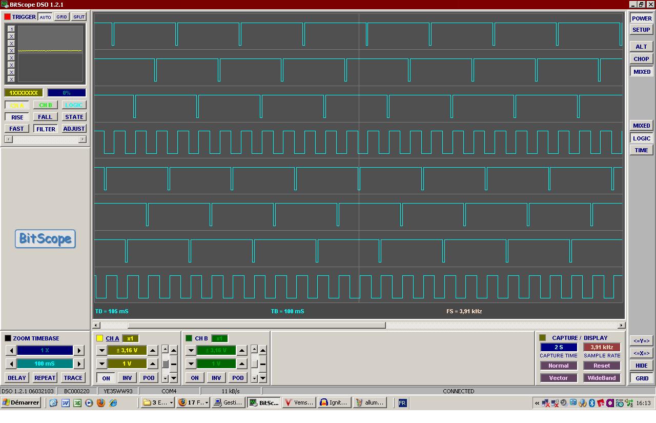
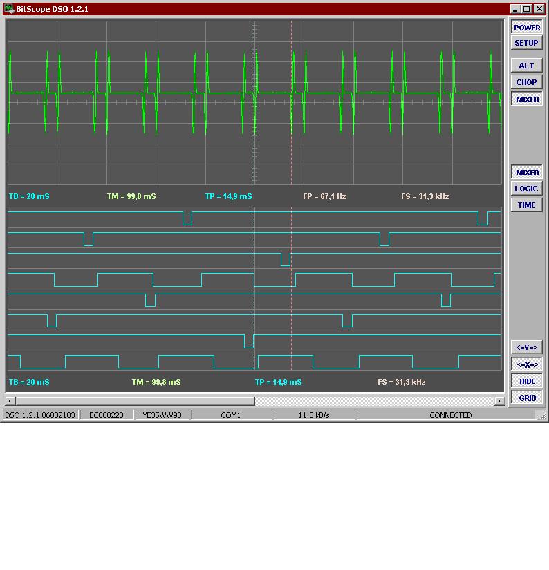
I made the Vems and Marelli Microplex running in // on a the bench. Vems EC26 Pin10 was for ignition bank A, Pin11 for bank B
After having tried TDC After Trigger =10, 40°, TDC After Trigger = 100° gave identical ignition signal respectively on each bank. It runs well for some time as seen on logic analyser
From top to down: Ignition BankA Mplx, BankA Vems, BankBMplx, BankB Vems. Ignition is done at rising edges.
This is perfect.
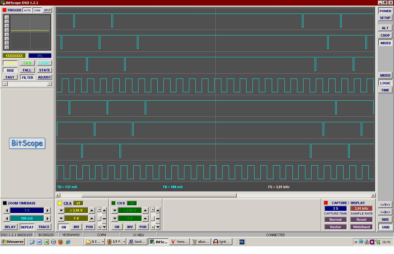
However later on, after switching on and off, testing a 5000 RPM .wav file(the signal from the trigger play is not strong enough to stimulate the Mplex at this speed) etc... I got some desync of Vems ignition
Besides I quoted that VemsTune shows off alarms from time to time: "Too many Primary Trigger" "Less sec trig" etc..
I should say that the 2nd LM1815 I fitted was for some reason in mode 3 Pin5=0V, that is input arming=0V. So I went to set mode 2 Pin5=5V (arming at 0.2V)but when I desolder some wires on the chip I had set to stimulate logical outputs, I think I burn it and I did not made tests for Mode2 Pin5=5V.
I cannot say if the desync of Vems ign out is a consequence of the trigger errors (my bench facilities are limited), but anyway If it is the case, one main point is that misplaced firing are done by Vems despite these error :
Does Vems handles these defaults?.
I think in case of non recoverable trigger error there should be no ignition. May be safer to have these features on firmware before running the ecu on the car.
First log files
I have recorded the following .vemsLog
http://www.vems.hu/files/MembersPage/Maserati/FPhil/Ign2011-06-05-1.vemslog
and triggerlog
http://www.vems.hu/files/MembersPage/Maserati/FPhil/Ign2011-06-05-2.triggerlog
http://www.vems.hu/files/MembersPage/Maserati/FPhil/Ign2011-06-05-1.triggerlog
".VemsLog files"
Alright I wanted to show the log history for
TriggerErrorType log + disp_spark10 + disp_spark11
from a .vemslog file.
So, after playing sometime with the menus options
- I created a MultiGraphDescriptor named dbgIgn, then
- I open the Editor to reference the data names, then
- I append new empty node (why is it called a node?), then
- I edit this empty node by giving the name of the data (say disp_spark10
-> does not work
Then I convert the .vemslog to .csv. -> Bug: it freeze at the end of the conversion Auto-close option ?
Anyway, fine tool but the data I wanted to watch was not recorded.
Allright, learning the hard way, I should have told VemsTune which data I wanted to log.
No No, no way, you cannot set your record profile.
Going to do something with the .csv file …
Suggestion : VemsTune is becoming a huge tool. Why not to split it and have an independent log viewer/analyser tool (weighting 80KO ;p) ) with easy access to basic functions!!
triggerlog files
Tried to read my triggerlogs on VemsTune stand alone with Tools/ Analyse/recordTriggerLog. The File is 165k.
- Show result ok but unable to copy part of the table to comment result
- save as .csv file and continue using text editor on .csv file.
- publish the file (maybe zip it) and comment like "10.8 sec of ... file".
- Maybe also take a characteristic screenshot of the graphical screen (alt-printscreen keypress and ctrl-v into paint program)
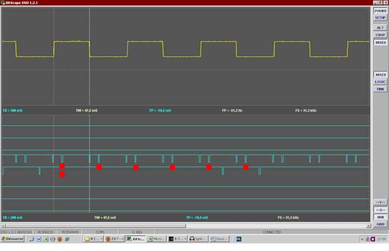
What I have noticed (see underneath):
- Primary time is alright 5ms, 15ms, 5ms, 15ms etc
(Remark : Primary dif takes the dif between last primary time and secondary time whenever a end trigger occurs between the 2 primary)
- At some moment there is a lot (say 7) of secondary pulses which are recorded at short time, the smaller being say every 0.024ms.
- When this occurs the primary pulses are separated by 20 ms, it means that one primary trigger is off
| 11 | 195.324(6) | 5.000 | 0.69 | |||
| 12 | 210.320(7) | 14.996 | 3.00 | MISSING TOOTH:2cycle=8 | ||
| 13 | 215.316(8) | 4.996 | 0.33 | |||
| 14 | 230.316(9) | 15.000 | 3.00 | MISSING TOOTH:2cycle=2 | ||
| 15 | 235.316(10) | 5.000 | 0.33 | |||
| 16 | 250.312(11) | 14.996 | 3.00 | MISSING TOOTH:2cycle=2 | ||
| 17 | 253.776(5) | 3.464 | ||||
| 18 | 253.800(6) | 0.024 | ||||
| 19 | 253.828(7) | 0.028 | ||||
| 20 | 253.856(8) | 0.028 | ||||
| 21 | 253.904(9) | 0.048 | ||||
| 22 | 253.928(10) | 0.024 | ||||
| 23 | 253.956(11) | 0.028 | ||||
| 24 | 254.884(12) | 0.928 | ||||
| 25 | 270.308(12) | 15.424 | 1.03 |
I measure the width of pulse out signal from the chip LM1815 as 0.030 ms. "Pulse width" is shown as 20-22 by VemsTune when running.
Hence the multi 2nd trigger pulses I get can be LM1815 related and due to the fact that I set the arming threshold to 0V by setting the mode 2.
I have to change the mode and the threshold (200mV Mode 3)
- Besides there chould be a time event filter on the secondary pulse.
- Otherwise I cannot explain the fact that one primary trigger is missing during this multi 2nd Trig period and the reason why the ignition was still firing despite the errors.
- no, there is no such software filter. I assume that HALL-dirac filtering is off. But even with HALL-dirac filtering, all incoming pulses are shown in triggerlog (sent to serial buffer before the HALL-dirac filter neglects the pulse).
- So the only "filter" is the serial baudrate (only effecting triggerlog analysis at high RPM, does not effect running), with 19200 baud (1920 bytes/sec) is above 900 pulses / sec (54000 pulses / minute), ~9000 RPM with a 6-tooth wheel
(Remark: The TriggerLog tools should use preferably ";" as separator instead of "," because "," is used in the log text and some parser still split cells even for "," in text enclosed by quotes.
- good point !
Successful Ignition Bench Tests
(June 2011)
I use for these tests the brand new ECU just received (SN V3.3_4003856).
VemsTune is 11-06-04
After some trials, I get the Firmware 1.1.91 uploaded.
I first redo the previous tests (see First Bench Tests) by running in // with Vems the car ignition ecu (Microplex) in order to compare the ignition outputs signal by pulldown resitors from 5V.
RESULTS
- Ignition bank A and bank B -> GOOD (see below)and No Trigger Error Flag, no phase out
- Robustness :
- I cut the 2nd trigger signal out
- Ignition stops -> GOOD
- On VemsTune screen : Temporary Trigger Error flag and Running On Message BAD - DOES IT MEAN THAT THE INJECTION IS STILL FLOWING DURING IGNITION OFF??
- Putting the 2nd signal back
- Ignition recover -> GOOD (see below).
- I cut the 2nd trigger signal out
- I did not test with noisy trigger signal
I then test dynamic ignition, firing each plugs separately. I set the following simple ignition config: 0 : I259-0, 1 : I259-1, ..., 5 : I259-5
RESULTS
- I got the following ignition output -> GOOD
- Robustness tests as above -> GOOD
On the VemsTune 2nd Ignition window, the one which figures out the output pins for the choosen ignition config, the ouput 0 appears in RED and an alarm message asks to "Press validate button for details" , I did so but nothing came up ???
(July 2011)
I replace the LM1815 (thanks for the mailed chip) on the other ECU (I burnt it during my first tests) and set the LM1815 mode to for 200mv threshold
- Uploading for firmware 1.1.94 and running same tests as above -> GOOD,
REMARKS
- "Running On" message on VemsTune although ignition off (see above)
- output 0 on Vemstune ignition window is in red (see above)
- Ignition on pin12 and on pin 36 are pull-up: this gives Vcc (5V) during dwell time and 0V either.
Ignition config concerns and solution
I thought that TDC = 100° and SparkDelay (SPD) of 0°,30°,0°,30° etc were good parameters for ignition pattern.
However I have not taken care of the Spark Angle from the ignition Map and pid attention to sync with crank triggger!
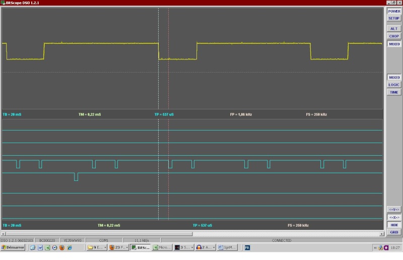
Setting Spark Angle=10° at 1000rpm and plotting ignition versus crank trigger gives:
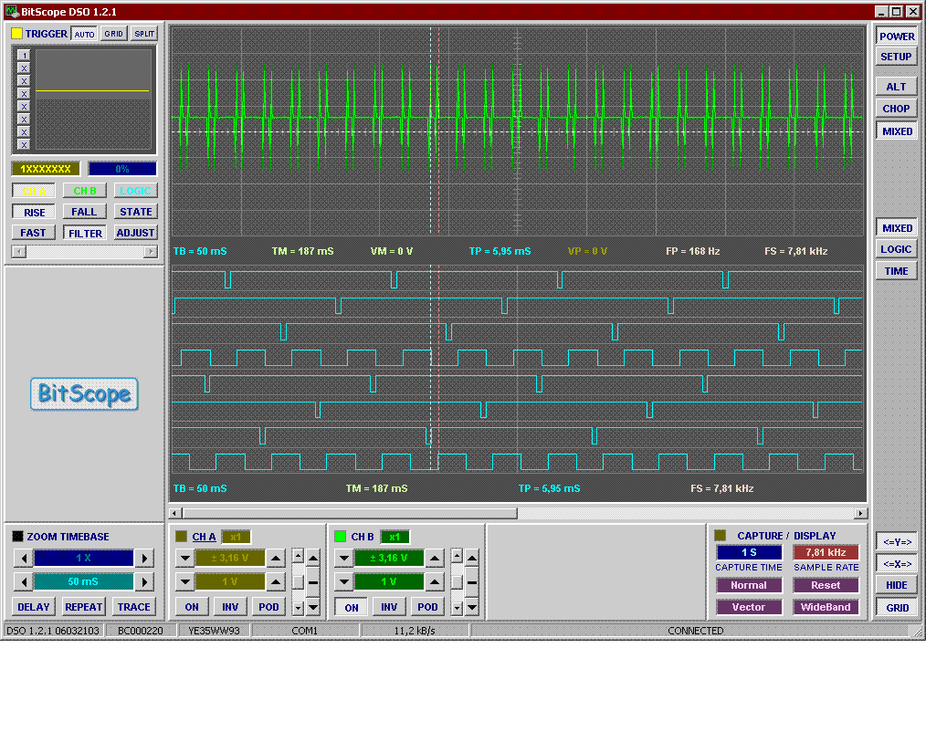
On that picture the logic plots n°4 and 8 are for MPlex ignition (bank A and B), SPA for Mplex is little more than 10° and crank trigger is 10° TDC
- Vems ignition with this config appears 30° off !!
I tried several other settings
- TDC=10° does not allow SPD
- TDC=127.5° and SPD 0 30 0 30 ... works (130°is not possible)
Finally I set TDC=100 and SPD 30 60 30 60... .With SPA=10° this gives:
Alternatively I could have set TDC=110 and SPD 20 50 20 50 ...
- Q: Depending on firmware, what is the best setting?
- use per cylinder ign delay as low as possible (even if ign tdcdelay is higher)
- so best is TDC=127 and SPD 03 33 03 33 ...
- no difference except during transients (=quick relative RPM-variations, eg. during cranking), even than minimal. Per cylinder spark delay is applied with a calculated time delay: will not use a later tooth even when it would be possible.
- I see... Indeed I get trigger error flag during accelerating transient with the 100-30-60 config. I would tried this one ... Hence 3 crank teeth is sufficient !!! I guess how good the angular velocity would be.
Copy of the biturbo ignition map to genboard
This biturbo map is a 16x16 array where lines are for MAP and columns for RPM. I found out the scale for the MAP, I also need the RPM scale precisely...
Alright I found out the coefficient and what the timer of the 6803U is doing. We would be able to do a good compare.
Q. The Ignition map from 1.1.94 appears to be a 12x12 table. I had to make choices when copying the 16X16 MPlex table onto Vems.
Why not run a 16x16 table as the 25 years old MPlex firmware does?
Inj outputs - same order as ign
Use the same injout entry as the ign (if topmost ign is, say, cyl3, topmost inj should be also cyl3 output for unbiased inj-angle positions).
---