Ignition parameters for odd fire coil type configuration.
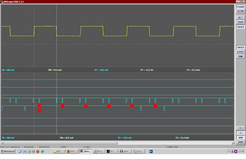
In the descriptions, let's always use the teeth after the short gap ( short gap=30 deg, not the long 90 deg gap) as a reference,
- either 1 certain tooth as a reference for all TDC marked with DOUBLE red dot on pic below.
- like: 10crankdegBTDC (cranking sparkadv) points are (ASSUMED - to be confirmed or corrected) 90, 240, 330, 480, 570, 720 degrees
- or the last such tooth marked with red dot on pic below (this, by itself does not cause a confusion since the tooth after shortgap are evenly spaced every 120 degrees so it's just "mod 120" deg of above values)
- like: 10crankdegBTDC (cranking sparkadv) points are (ASSUMED - to be confirmed or corrected) 90, 0, 90, 0, 90, 0 degrees
All non-conforming descriptions should be changed or deleted. Any misunderstanding can result in problems and lotsof wasted time for all involved.
As I understand, the Marelli microplex logic for starting the ignition is:
| On CamTooth 1 | START COUNT Crank teeth |
| On CamTooth 2 | (after short 30 deg gap) when CrankCount=2 then START IGNITION, cyl2 cranking sparkadv is 90° from here |
Cyl2 TDC is 100 degrees from that Crankcount=2 pulse.
In software they simply made a switch for the 12 cases
given by the 12 teeth met in a 720° cycle.
- Also they simply put a constant 120° dwell time
- (but this is too long at low RPM)
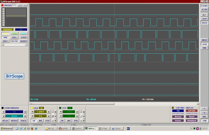
BLEU : IgnitBiturbo1000.wav - JAUNE: IgnA - VERT IgnB
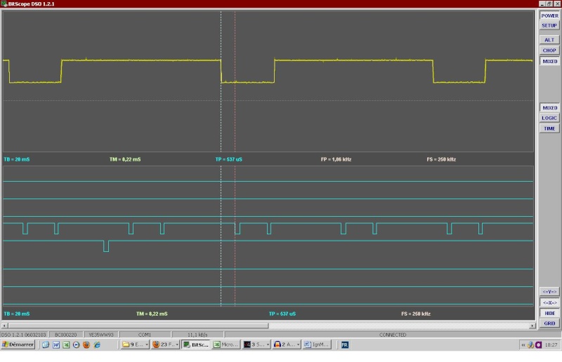
Lets note the 6 tuples of 2 crank teeth which are seen by the VR sensor during a double revolution of 720 ° by the following:
/t01/.30°./t02/ .. 90°.. /t03/.30°./t04/ .. 90°.. /t05/.30°./t06/ 90°
/t11/.30°./t12/ .. 90°.. /t13/30°/t14/ .. 90°.. /t15/.30°./t16/ 90°
Genboard has to fire 10° before the following teeth
/t01/ ..... 150° .... /t04/ .. 90°.. /t05/ ..... 150° ....
/t12/ .. 90°.. /t13/ ..... 150° .... /t16/ .. 90°..
Can we do odd firing with coil type triggers?
Answer
- so download the config above, or from MembersPage/OddFireSixCyl
- dragndrop file to relevant dialogs ("primary trigger", "reftooth table"). This is the quick way to import the displayed settings (changed entries change to red)
- the ign outputs must be set to your ignout wiring
- the triggerlog also shows the spark events, so examine that too (and use the strobelight) before actually trying to start the engine
- yes, the showed configs used the individual cylinder spark delay 0,30,0,30,0,30 to make 90,150,90,150,90,150 "odd-fire" sequence from the even 120,120,... sequence.
Anyway I don't even know on which crank tooth Firmware 1.1.90 start counting. I should make a triggerlog next time.
As for the use of spark delay, I think I have understood :
Because of the odd fire configuration of genboard, it remains 6 reference trigger pulse per double cycle from the 12 crank triggers, hence they are 120 ° apart. That is
/t01/. 120°.. /t03/.120°.. /t05/.. 120°
/t11/..120° /t13/ ..120° /t15/..120°
or
/t02/. 120°.. /t04/.120° etc depending of when firmware does the sync from the cam trigger (I have to find out that)
Indeed if we note d03,d11, d15 the ignition events delayed by 30°, we get what we need:
/t01/.150°. /d03/.90°./t05/. 150°. /d11/.90°./t13/.150°/d15/. 90°.
Help for ignout config
So that we can help with ignout config that matches your wiring, fill this in:
- What is the exact position of the 2 primtrig pulses coming after the second sectrig pulse ?
- What is the cylinder that follows ?
- which ignout is that connected to ?
- than list the remaining (5) cyl / ignout entries
- always mark the angle separation between the cyl/ignout entries (in a separate line, to be clear, 150 or 90 degrees)
Answer
I am not yet at this point. I would connect the firings lines (with diodes)* for the bank A all together, do the same for bank B and fire the engine through the distributor the same way it is done with the Microplex (we are still far from there).
I finally understood that this is useless since it is possible to drive freely any ignition event to any ignition output of the genboard (yes Versatility)!! and this is already done by the config file since
h[2]=70 40 70 40 70 40 70 70
As we see only 2 output ports are used in order to fire the cylinders of bankA or bank B.
Of course now one needs to know which is which and the Triggerlog which now records the ignitions events would be of great help for that.
I also found out the delay parameters from the VemsTune menus "Cyl separated Spark delay" and was surprised to see it is already set as one wanted, this is also define, I presume, by the table h[3] of the config file (MembersPage/OddFireSixCyl):
h[3]=00 78 00 78 00 78 00 00
because 0x78 = 120 = 4*30°.
Bench tests
- Here after some bench test from the board ...
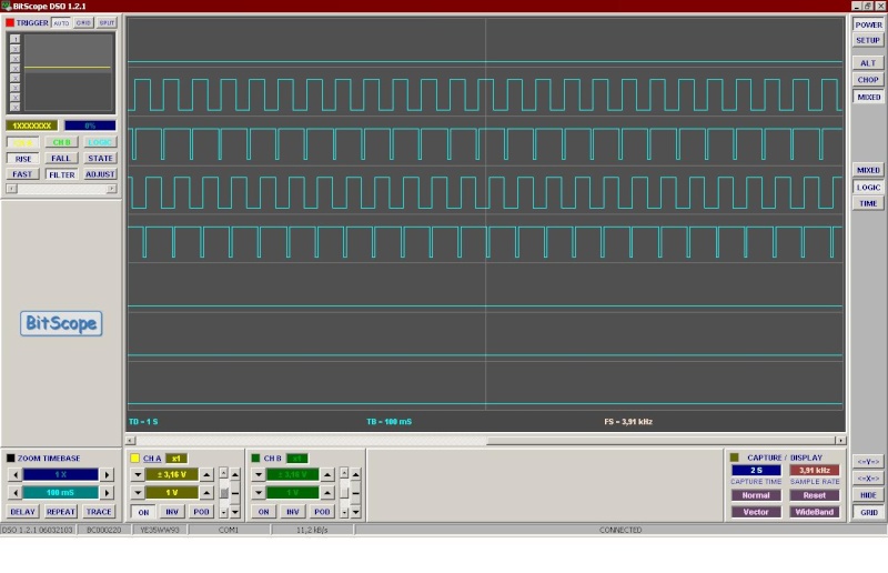
- Bench tested scope shot showing the requested timing:
- ch1 : secondary trigger
- ch2 : primary trigger
- ch3 : ignition output ( all slots set to same output in this test )
- Full [here]. Change the following:
- we used same ignition output in all 6 slots to make it easier to scope (use 6 different outputs in real life, that drives the 6 transformers)
- set ign TDC delay (apparently lower than 40 degree also seemed to work, even during cranking)
- swap the 0,30,0,30,0,30 in the "individual spark delay" table to 30,0,30,0,30,0 if necessary
- Then mine ...
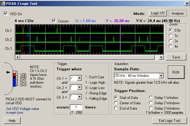
I made the Vems and Marelli Microplex running in // on a the bench. Vems EC26 Pin10 was for ignition bank A, Pin11 for bank B
I set TDC After Trigger = 100° to get identical ignition signal respectively on each bank. It runs well for some time as seen on logic analyser
From top to down: Ignition BankA Mplx, BankA Vems, BankBMplx, BankB Vems. Ignition is done at rising edges.
This is perfect.
However later on, after switching on and off, testing a 5000 RPM .wav file(the signal from the trigger play is not strong enough to stimulate the Mplex at this speed) etc... I got some desync of Vems ignition
Besides I quoted that VemsTune shows off alarms from time to time: "Too many Primary Trigger" "Less sec trig" etc..
I should say that the 2nd LM1815 I fitted was for some reason in mode 3 Pin5=0V, that is input arming=0V. So I went to set mode 2 Pin5=5V (arming at 0.2V)but when I desolder some wires on the chip I had set to stimulate logical outputs, I think I burn it and I did not made tests for Mode2 Pin5=5V.
I cannot say if the desync of Vems ign out is a consequence of the trigger errors (my bench facilities are limited), but anyway If it is the case, one main point is that misplaced firing are done by Vems despite these error :
Does Vems handles these defaults?.
I think in case of non recoverable trigger error there should be no ignition. May be safer to have these features on firmware before running the ecu on the car.
Copy of the biturbo ignition map to genboard
This biturbo map is a 16x16 array where lines are for MAP and columns for RPM. I found out the scale for the MAP, I also need the RPM scale precisely...
Inj outputs - same order as ign
Use the same injout entry as the ign (if topmost ign is, say, cyl3, topmost inj should be also cyl3 output for unbiased inj-angle positions).