Adapting v3.2 ecu to the Toyota MR2 with the 3S-GTE, 2 liter inline 4 cylinder, turbocharged engine.
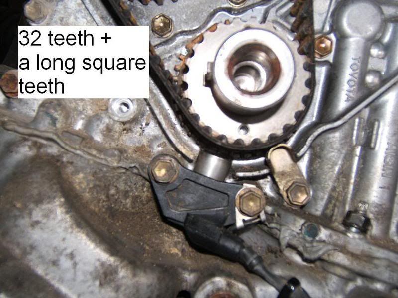
- Toyota OEM cranktrigger (32 + 4 tooth or something) system is not used. Instead of 60-2 wheel fitted to the crankshaft. Toyota OEM VR sensor is located to read the 60-2 type wheel. First tooth after trigger (ie. missing tooths) is located to 90 degrees before cylinder one is at TDC.
MembersPage/PhatBob Don't write off the Toyota trigger! its a 24+1 trigger which I've tested off the car and had some good results with. The 22tooth Ne sensor goes to the primary trigger, and them the G1 sensor acts as the secondary (sync).
- No it is not 24+1 type, it has 32 tooth wheel in 4th gen. 3S-GTE engine, with one long tooth. Trigger wheel part number is: 13521-88560
MembersPage/PhatBob You mean like this one?
I can't see what would be wrong with that at all, a long tooth will be regarded in the same way as a gap for a missing tooth arangement, we've got a similar thing with the Renault flywheel trigger.
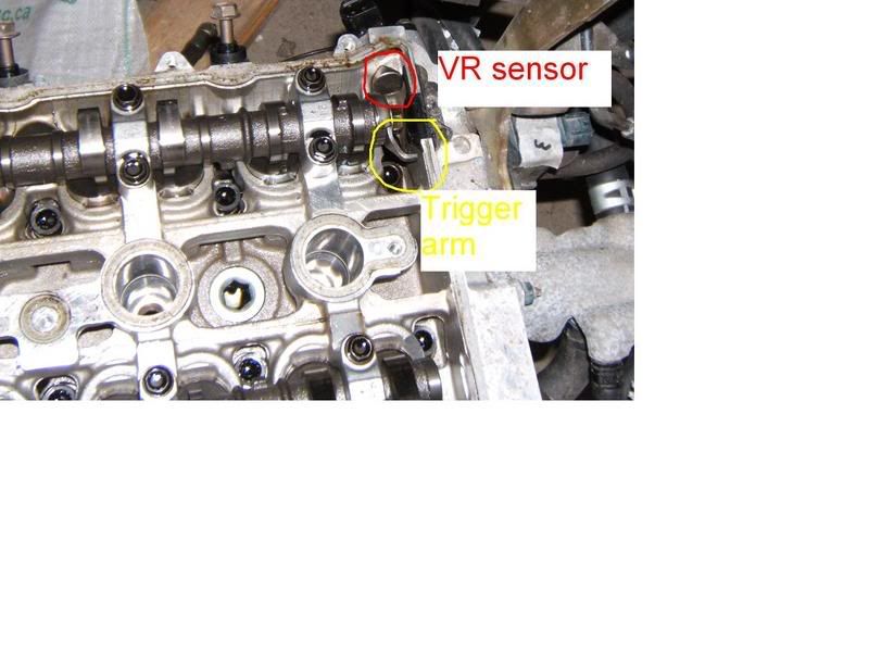
Also with the cam trigger:
You have a perfectly good solution.
It has to be worth a try before going for an aftermarket 60-2 trigger.
Firmware version 1.1.23.
- Is this latest release version, download page is little bit confusing ?
This release has 12x12 and 16x14 compiled firmware in hex form. Downloaded 16x14 version to the ecu, but the signature does not match (when starting Megatune).
Made an workaround by editing conditional line detection strings in Vemv3.ini
Something wrong, with the package or did we have an procedural error ?
Coil on plug installation (Denso pen type coils from Renault Laguna are used).
Denso four hole injectors (flow rate 450 cm3/min). Bosch knock sensor. Bosch idle valve, double coil type
Toyota OEM IAT and CLT sensors
- is there characteristic curve table for these sensors ?
MembersPage/PhatBob Use the 2252 bins for IAT and CLT.
One electrical problem arised.
- Map (internal MPX4250 -> 250 kPa sensor) displays wrong pressure (around 29 kPa when exposed to atmospheric pressure).
- MAP value increases (in fact it rails) when throttle is opened to 255 kPa.
Solved: MAP Sensor was incorrectly soldered upside down (-> pin is was located left pad on PCB).
Question:
Should there be separate jumper wire from 5 volt source to the internal MAP sensor pin 1 ?
Knowledge for the ECU setup is somewhat needed;
Could not get Manmlp07 command to work, ecu does not respond to it. Man and bye commands work, but no response for the Manmlp00 to Manmlp07.
Is these commands changed/dropped in these later firmware releases (than 1.0.19 which is the most familiar telease to me) ?
- h(0) table values. Suppose these are hexadecimal values translated to the decimal representation (in Megatune). Table values in below.
- Injector channels h[0] masks
- Inj 1 EC36-7 / 01
- Inj 2 EC36-19 / 02
- Inj 3 EC36-8 / 04
- Inj 4 EC36-20 / 08
- Inj 5 EC36-9 / 10
- Inj 6 EC36-18 / 20
- h[0] set to order of (Toyota 3S-GTE engine) firing (1-3-4-2).
- Note h[0] table is read "backwards"
- When cylinder 1 fires, inlet stroke begins in cylinder 4.
- firing inlet
- 1 4
- 3 2
- 4 1
- 2 3
- 3 1 2 4
h[0]=04 01 02 08 10 20 40 80
MembersPage/PhatBob You want to inject onto the firing cylinder's port - the heat of combustion will help the fuel evaporate better. Injecting onto an open valve can cause high Hydrocarbon readings on a proper gas analyser and bad idle quality.
Ignition channels used 00..03
(00=cylinder 1, 01=cyl2, 02=cyl3, 04=cyl4)
h(2) (and h(1)) table settings not yet defined.
I will post mcd and mct after the MAP problem cleared.