Planning VEMS 3.3 for turbocharging BMW M50B25 engine in an BMW E36. Lives in Sweden Gothenburg.

M50b25
- 2500cc
- 6-cyl
- 24valve
- Vanos removed
- Firing order: 1-5-3-6-2-4
- Hp goal ~400hp@bar
Enigne Spec:
- M50b25 without vanos
- Je Forged Pistons Compression 8,1:0
- MLS headgaskset 1,8mm
- ARP headstuds
- 500cc injector
- Preicison Turbo SC-44
- Tial 38mm wastegate
- 50mm PPF blow-off.
- 600x300x75mm intercooler
- Sachs heavy pressureplate 240mm
- Organic disc 550nm
- Walbro 255l/h fuelpump
- Primary trigger: VR
- Cam Trigger: VR
Question about WBO2
I'm still struggeling with the WB02. When I turn it on, Ri and Nernst begins to fluctate and Heater increase, Pump=64.
Then when the O2% value shows up, the values ("what values?" like voltage measurements? or on LCD?) of heater and Pump and O2% begins to fluctate.
- I have also noticed when it's turned on, the box begins to give away a sound (it sounds like an airleak does).
- this is likely because of the heater current. It shouldn't be a problem by itself.
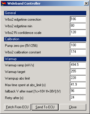
I'm using the exact same configration values on the widebandsetting as the manual, and use my own pump_zero value. Here a log from the mlp07 page with 0.5s intervall. http://83.227.224.152/bmwturbo/bb.txt.
I have also notic that the only stable value on this page is AFR=14.83, except when TPS>50%. When this happens it goes down to 11.37. Does it seems like something is broken on the board or is it maybe some noise, or else? The wiring is correct, have checked it several times now. I have been told that the heat should be much higher, may the problem depend on this?
TODO: complete the info to contain the minimal information necessary to review (peek at IssueReports)
- firmware version: 1.0.23
- full mcd/mct dump (NOT megatune snapshot images or msq)
- mcd Config : http://83.227.224.152/bmwturbo/config.txt I used the same WBO2 config as "bostrom.msq": now i have a stable O2 reading but still the box sounds and the others value (what is "others value"?) fluctates.
- and mct dumps Tables - >http://83.227.224.152/bmwturbo/tables.txt
- The sensor is brand new, from the webshop (no previous abuse from bad connection or config).
- wbo2_nernstdc_target=8D ... maybe 9C is better,
- document your board serial NR
- if you have a MAP voltage => kPa reading measurement, that would be useful too
- wbo2_calibration=CB
- document your sensor's measured Rcal resistance (say, 122 Ohm between sensor pin2 and pin6)
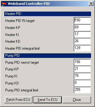
- wbo2_pump_pid_kd=08 use 00, I don't see any reason for 08
- please point us to the bad recommendation of wbo2_pump_pid_kd=08 so we can correct it.
Question about ING_DUALOUT
Going to startup the car soon and going to start with wastedspark first. I have compiled a firmware with ign_dualout and is now setting up the config to get this work. I have a preassembled box with 6-2ign option which means ign channel 03 and 05 are set up for logical levels. Therefore i can't use conf a'la Dave as recommended the manual as i would if I had the ign channels in row 00..05. The firing order is 1-5-3-6-2-4:
- COP 1 = ch00
- COP 2 = ch01
- COP 3 = ch02
- COP 4 = ch04
- COP 5 = ch06
- COP 6 = ch07
Is it correct then to set up up ignchmax=05 and h[2]=04 01 07 02 06 00 00 00 ?
This seems good, assuming that cyl4 fires after your camsync pulse (selected edge) comes, therefore you start with cyl5.
If this is not the case, rotate the order accordingly (and write the 1-5-3-6-2-4 as .... ).
Began to calibrate the sensors today. Started with WB02.Used the config from the manual and added my pump_pw_zero:0x64. When i then tried to calibrate the O2% the values were unstable and hade a difference between 20.5-21.5. All values on mlp07 page were unstable except AFR. Any suggestion?
Then i began with EGT. Boiled it at and set the value on 100C. On ice it showed 0 C. Then i put it onto gasflame on a lighter. 880 degress just above the flame. Shouldn't this be 677C? At 15 in the garage it showed 11C. Only changed multipler, the offset didn't change anything.
The IAT and CLT:
- Ref - IAT - CLT
- 0 - 0 - (-3)
- 22 - 24 - 19
- 64 - 65 - 61
- 100 - 99 - 94
Should i be satisfied with this or should i try a diffrent temp sensor file? The reference temp is taken by a normal thermometer
Q: The wiring is almost done, 80% done. Have made a piout table, but unsure about how to wire the knock A&B. Also unsure about the Idle Air Control Valve. It's a Bosch 0 280 140 545 1738 981. It has 3 pins. I guess one is ground, the second 12v supply and the third should be connect to injector #7 or #8?
- is it same as MembersPage/GergelyLezsak/IdleControl ?
Q: I measured the trigger angle 60 degrees before TDC.
- that is perfect, 40..100 degrees are OK, and 40..60degrees is the best.
Q: I want a tachometer signal to the stock rpm gauge. How should i set this up? Is there an output for this, and can vems handle this when I'm using COP?
- use a separate output, and configure config.tach_channel and config.tach_divider; If you have no luck (review, measure, publish, but) consider that some RPM gauges require high input voltage signal which can be derived from the ignition transformer primary (using a few diodes).
The stock wiring scheme: http://www.autolib.diakom.ru:8001/CAR/BMW/1992/325%20Series/WIRING%20DIAGRAMS/11.pdf
Pin out:
| Function | EconoSeal pin |
| Sensor power 5V | 36-28 |
| Sensor ground | 36-26 |
| Power ground | 36-5 |
| Power ground | 36-21 |
| Power ground | 36-22 |
| Power ground | 36-32 |
| Flyback | 36-23 |
| injector 1 | 36-7 (Injector A) |
| injector 2 | 36-19 (Injector B) |
| injector 3 | 36-8 (Injector C) |
| injector 4 | 36-20 (Injector D) |
| injector 5 | 36-9 (Injector E) |
| injector 6 | 36-18 (Injector F) |
| CLT | 36-14 (CLT Coolant Temp) |
| IAT | 36-2 (Intake Air Temp) |
| TPS | 36-1 (TPS signal) |
| TPS 5v | 36-28 (TPS +5v) |
| IAC | ? |
| Crank position sensor (vr) | 36-27 |
| Cam position sensor (vr) | 18-13 |
| knock signal A | EC18-2 |
| knock signal B | EC18-3 |
| coil1 | 36-35 (Coil #1) |
| coil2 | 36-33 (Coil #2) |
| coil3 | 36-34 (Coil #3) |
| coil4 | 36-11 (Coil #4) |
| coil5 | 36-24 (Coil #5) |
| coil6 | 36-10 (Coil #6) |
| Fuel Pump Relay | 36-15 |
| nernst_cell | 18-13 |
| heater - | 18-18 |
| pump - | 18-7 |
| pump + | 18-9 |