See
- GenBoard/VerThree/Schematic
- BroadcastDatastreamAimSecondSerial (5V often used for 2nd COM wiring DSUB9/pin9 +5V for BT-RS232
5V is on several places, eg. on the 4pin PS2 (optionally wheelspeed) header seen here:
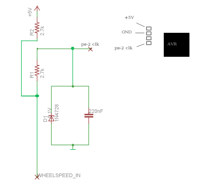
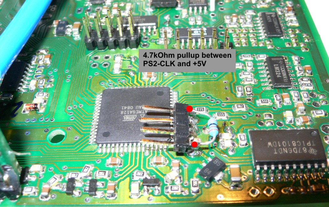
On the 4 pin header, the pad of the pullup resistor on the image (viewed from endplate, so upside down compared to original PCB layout), which is closest to PCB edge.
For BT-RS232 any 78L05 (SOT89) output (pin1) would do.
Eg. the 78L05 between EC36 and EC18 close to the econoseal PCBedge can be used (otherwise unused).
Main 5V - strongest (but take care)
The 5V from MC33269-DT5 main regulator is available direct next to the 3pin 2nd RS232 header (and strongest 5V actually, enough current for wifi-serial also; but accidentally shorting the main 5V due to incorrect installation would adversely effect mainboard operation).
TODO: add PCB layout, with some or all of the 5V pads annotated with arrow (perhaps the otherwise unused 5V with yellow, the main 5V with purple, the others like LCD5V with red arrow).