Changes by last author:
Changed:
| We noticed that some multitooth triggers will false trigg at high rpm, the genboard kill the engine until the trigger signal is stable again. |
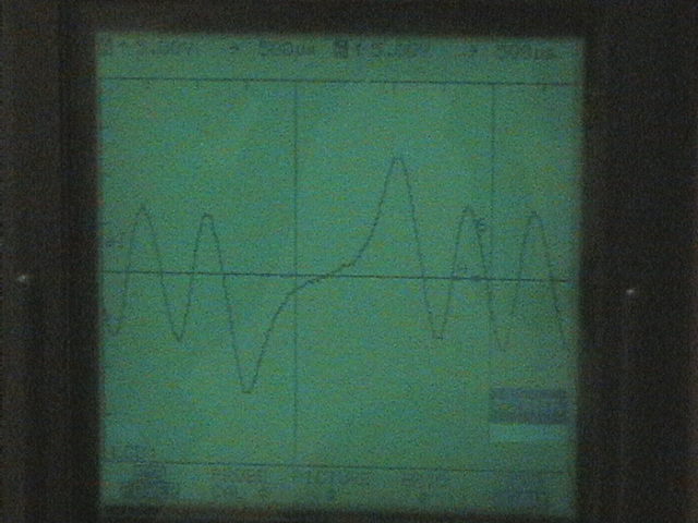
| Deviant trigger signals - higher amplitude at the missing tooth |
| This only happens with multitooth triggers with missing _teeth_ instead of missing _gaps_. It seems like the resonance in the trigger cause a trigg even if there is no tooth. Let's just accept that something cause it to trigg... |
|
This only happens with multitooth triggers with missing teeth instead of missing gaps.
The standard Bosch 60-2 wheel has similar amplitude at the missing teeth (because of the height-profile used) as for normal teeth, so it is not effected. Note that v3.3 was modified to push adaptive threshold down as in the solution below with R181 (and R182 for secondary trigger VR circuit). * R181=100k..180k, as shipped from factory, makes it possible to run deviant VR signals like the one below. On v3.0 .. v3.2 a small tracecut had to be done to solder the resistor (usually 150k in series with C38) that pushes down adaptive threshold * R181=0k pushes adaptive threshold up to maximum, as the original behaviour. This should not be needed, unless VR signal is noisy like trash but otherwise not deviant at the missing tooth like the one below. |
| The trigg is much lower amplitude then the trigg caused by the real teeth, but the imput protection cause all triggs to be cut to 5v, this also prevent the arm threshold from rising above this level. The arm threshold is meant to prevent any signal lower the 80-90% of the main pulse train from trigging the circuit. |
| How do we solve this? |
| Problem |
| One way would be to use a voltage divider on the sensor to decrease the amplitude of the false trigg. As long as the real triggs is more then 100mV while cranking we should be fine. |
|
| Using an RC filter with an R in paralell with the C, on the input could also work, that way we could almost leave the amplitude while cranking untouched while slowly increasing the damping with higher rpm. |
|
Deviant multitooth VR signal
* There is a HIGH peak at the amplitude around the missing tooth. This causes the peak detector cap to charge to a high level * Otherwise correct polarity: lm1815 triggers on negative going zero crossing, there is a good illustration [here on page 8]. |
| Using an compressor would also work, that way we could keep the amplitude of the signal conditioned signal at a set level regardless of the amplitude from the VR sensor. |
| TODO: Could someone record or make a wav so we could play with it on table ? |
| ---- |
| We noticed that (with deviant trigger, and original high-adaptive threshold setup) some multitooth triggers will miss trigg at high (?? not low?) RPM, genboard shuts down inj and ign until the trigger signal is stable again. |
| I had some problems with trigger at high > 3000 rpm. When looking at the scope I found the problem. There is a HIGH peak at the amplitude around the missing tooth. This causes the peak detector cap to charge to a high level. |
|
Note: input protection cause all triggs to be cut to 5v, this also prevent the arming threshold from rising above this level (so at high RPM there shouldn't be any problem! Only at low-RPM could there be problem, right?)
The arming threshold is meant to prevent any (noise) signal lower the 80-90% of the main pulse train from trigging the circuit. ---- Solution |
| I guess that running the lm1815 in mode 2(pin5 to VCC). Would solve the problem. But I want to run the lm1815 in adaptive mode. So I solved the problem by connecting a 100k resistor in series with the Peak detector cap. This resistors serves 2 purposes: |
| I guess that running the lm1815 in mode 2(pin5 to VCC). Would solve the problem. But I want to run the lm1815 in adaptive mode. So I solved the problem by connecting a 100k resistor in series with the Peak detector cap, C38. This resistors serves 2 purposes: |
|
I put the cap and the resistor standing on the board and soldered them together on the top. Definitely worths to put the possibility onto v3.3.
I guess that the resistor could solve the runout problem and solve MembersPage/SamuelLindkvist problem without making a new triggerwheel. I was horrified at the 90% worst case threshold of the LM1815 (probably no such chip in real life, but...) - that can be fixed this way. |
| Installed onboard in factory since v3.3 (slightly different configuration, but same effect) |
|
Could someone record or make a wav so we could play with it on table ? This is NOT reversed polarity. (sorry for the confusion: someone said on irc that it's reverse, and when I checked with a peek it somehow looked reverse to me). Right polarity: lm1815 triggers on negative going zero crossing, there is a good illustration on: |
|
----
VR HW testing - also useful for testing firmware behaviour with noisy signals Thinking about a small C program that mixes and plays A.wav and B.wav, fading from: 1:0 => 0:1 |
| Making the peak-detector rise slower and threshold lower (as described above) could-should fix the problem. But why would it not work by default? The input of the LM1815 is clamped to +500mv and -350mv. The high peak should NOT make a difference. |
|
Uses a normal signal and the deviant (see above) signal.
I found a codelet (from a lightweight fullduplex karaoke program I wrote for my father years ago) that is suitable to mix 2 trigger signals. |
|
If you look at the datasheet you'll see that the signal will rise above 0.5v for high input signals.
There is a graph showing 1.5v at pin 3 when the input signal is 30v with 20k resistor. |
| Commited to SubVersionSvn https://svn.x-dsl.hu/svn/firmware/testing/signalgenerator |
| You are right, a fast analysis of the internal schematic reveals a 1k series resisistor on the clamp. With our 10k ->zener clamp -> 10k input we could see 1v at pin3. There is an other possible path to gnd with a 500ohm series resistor but I would have to follow the entire schematic to figure out what it is. |
|
* dsp_rec.c was used to full-duplex play and record wav files
* add.c was used to mix 2 files (run as a batch-process) * we want to merge the 2 programs so 2 files are read from disc, added and played again and again, with fading from A.wav to B.wav happening at a specified rate * alternatively, some offtheshelf mixing program might be suitable (audacity?) Usage examples # if A.wav and B.wav are a normal and a peaky-at-the-missing-tooth VR but otherwised syncronized, we can test the adaptive threshold of a particular LM1815 chip and R181 resistor (100 .. 180k) # we can mix noise to a signal and see how it is tolerated (VR HW and firmware) # if B.wav is silence, we can fade the signal to see the smallest detected signal # other applications |
| This is good, it means that the series resistor on the peak detector cap is good. It may also indicate that dropping the input zener would have fixed the problem with the Köhler trigger wheel... |