Changes by last author:
Changed:
|
* can be installed inside the ECM case
** or outside (if the assembled v3 is equipped with 30V flyback and IRF640 200V FETs, which is default since 2010-12). |
|
* normally installed inside the ECM case
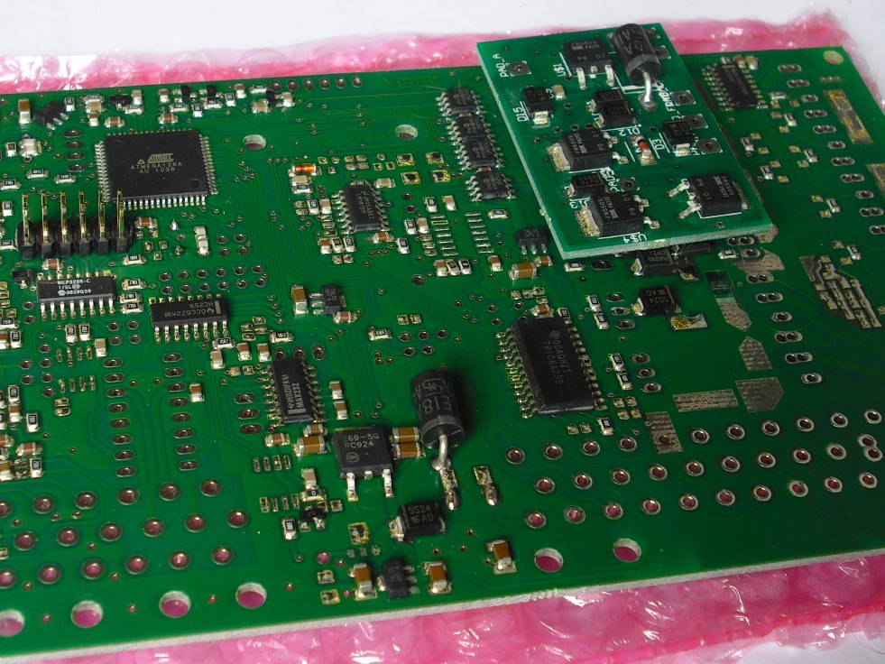
** the EC36/23 flyback pin (which goes to the injector +12V in the harness) must be connected with min 0.75mm2 wire to the anode of big throughole "1k5e30" 30V unidir transient diode on the extension board * alternatively outside (if the assembled v3 is equipped with 30V flyback and IRF640 200V FETs, which is default since 2010-12). |
|
|
|
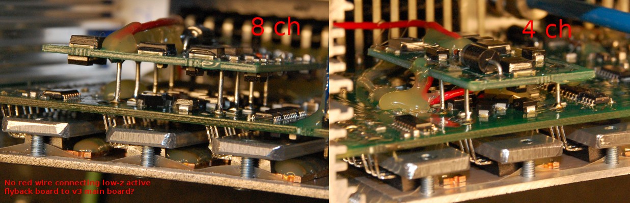
In case of the 4ch lowZ-extension only: * from the mainboard flyback rail (if the 30V unidir transient diode is missing from the mainboard for mechanical clearance reasons) a 0.75mm2 (red on the pic) wire is connected to the cathode of the 30V unidir transient diode (on the extension board). ** This completes the flyback path for the 4ch that does NOT have the low-Z extension => therefore not needed for the 8 channel extension |