The CPC 24 position plug will be wired as follows:
| Function | EconoSeal pin | Harness Colour | Chassis Plug |
| Sensor power 5V | 36-28 (+5V to sensors) | Orange | 2 (orange) |
| Sensor ground | 36-26 | Black | 1 (black) |
| Power ground | 36-5 | brown (chassis) | |
| Power ground | 36-21 | brown (chassis) | |
| Power ground | 36-32 | Black (chassis) | |
| Flyback | 36-23 | green | |
| Inj common +12V | 36-25 | 3 (red) | |
| injector 1 | 36-7 (Injector A) | Red | 4 (red) |
| injector 2 | 36-19 (Injector B) | gray | 5 (gray) |
| injector 3 | 36-8 (Injector C) | Purple | 6 (purple) |
| injector 4 | 36-20 (Injector D) | yellow | 7 (yellow) |
| CLT | 36-14 (CLT Coolant Temp) | lt brown | 18 (lt brown) |
| IAT | 36-2 (Intake Air Temp) | Pink | 19 (pink) |
| TPS | 36-1 (TPS signal) | Green | 20 (green) |
| MAP | 36-6 | pink | 21 |
| crank position sensor | 36-27 (Primary Trigger) | Blue | 22 (gray) |
| cam position sensor | 36-13 (Secondary Trigger) | Purple | 23 (purple) |
| knock signal | 18-3 | 24 | |
| knock ground | 1 (black) | ||
| iac | 36-34 Coil #2 | orange | 12 (red blue) |
| Oil pressure | cluster light | ||
| reverse lights | chassis electrical | ||
| turbo bulb on dash | 36-24 (Coil #6) | chassis | |
| CEL bulb on dash | 36-10 (Coil #7) | gray | chassis |
| Coil common | 3 (red) | ||
| coil1 | 36-35 (Coil #0) | white | 8 |
| coil2 | 36-33 (Coil #1) | brown | 9 |
| Cluster RPM Gauge | 36-12 (Coil #5) | gray | Chassis electrical |
| baro | 17 | ||
| boost solenoid | 36-36 (Coil #3) | gray | 10 |
| cooling fan | 36-11 (Coil #4) | red (black) | chassis electrical |
| Fuel Pump Relay | 36-15 | light Green | Chassis electrical |
| nernst_cell | 18-13 | blue | WBO2 connector |
| heater - | 18-18 | white | WBO2 connector |
| pump - | 18-7 | yellow | WBO2 connector |
| pump + | 18-9 | green | WBO2 connector |
Keyboard connection
| JP_PS1 | DB_15 | Signal | Cable Colour | PS/2 Pin |
| 1 (top) | 10 | VCC | Yellow | 4 |
| 2 | 11 | GND | Orange | 3 |
| 3 | 12 | Data | Brown | 1 |
| 4 (bottom) | 13 | Clock | Green | 5 |
Distributor Wiring
| Distributor Pin | Factory Colour | Signal |
| 1 | Black / Lt Green | GND |
| 2 | White / Red | +12V |
| 3 | White / Brown Spots | Trigger 1 |
| 4 | Yellow / Blue | Trigger 2 |
Now triggering is a problem here. Fero figured out the location of the slots so I didn't have to.
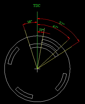
When fed with 12V the trigger2 outputs 5V or 0. Great for the hall trigger setup. Thanks again to Fero. When the crank trigger is hooked up to the board it measures about 3.8v and 150mv.