This car uses Genboard v3.2 #204 that has seen use in a Volvo PV : MembersPage/MattiasSandgren/VolvoPV
It never worked quite ok on that car, blew a few injector FETs and drivers.. long story. Emil sent the board off to be repaired with new FETs and FET drivers, and it was never tested with anything connected to a FET after that. Gustav bought the board and tested it on his SAAB, ignition only, and it worked very well.
When it was time to try injector it didn't turn out too well. As soon as the power is turned on, the injector outputs go active by default, instead of the normally inactive state. The function is inverted and the PA0 - PA07 pins are all set high (5.0 VCC).
What seems ok:
- Injector FETs
- FET drivers
- On the board right now : LM5111-1M (double non-inverting)
- Configuration (no injector outputs in use)
- Firmware (1.0.36 and 1.0.73 were tested)
What was never clear was the relationship between :
- Genboard hardware (FET drivers)
- Bootloader (that loads the VEMS firmware)
- VEMS firmware (application)
From what we (Mattias and Pelle) have deduced, one simply must have a firmware/application compiled for the type of FET driver on the board, this information is only given by the information that is compiled into the firmware/application.
What confused me a bit was that this was not what Jörgen said, he meant that the firmware/application took it's information about the FET drivers from the bootloader, so one simply had to have the correct bootloader to match the hardware to make the firmware/application work as supposed to. It isn't currently like that but was maybe true for the first Genboard versions.
The bootloader sets the outputs to safe defaults depending on what FET drivers are mounted. That's all it does, and implies that the firmware/application must have the information about the FET drivers compiled in as well to treat the outputs correctly.
We will replace the non-inverting drivers with regular inverting drivers (that are supported by VEMS firmware/application code).
We cleared EEPROM - factory restored, then did basic configuration. But as soon as power was applied the outputs were active. If the processor RESET line was set (active low) the outputs were active until we fixed the mixup with R153/R154.
We tried our own short and very basic code to test the injector outputs. We got the same behaviour as with the VEMS firmware from the outputs when we explicitly set the corresponding output to be an output (not input) and set it high. As we don't have the source code we can't tell what the other pins are set to.
We suspect a hardware issue, that we can't pin-point. At the same time the schematic reveals only OC0 and PA0-PA7 and these seem to behave like they should with our own code. So no other pins or components should pose a possible problem. Right?
What does the VEMS firmware do wrong that we do right? Still the firmware can't be blamed, it works on other boards, but the methods used seem to have the wrong effect on this board.
Early boards like this one used non-inverting FET drivers. Is this a case of the wrong boot loader used with the wrong firwmare?
What information does the bootloader contain? What is the correct bootloader version to use for this board? What does the firmware know or assume about the FET drivers state and function?
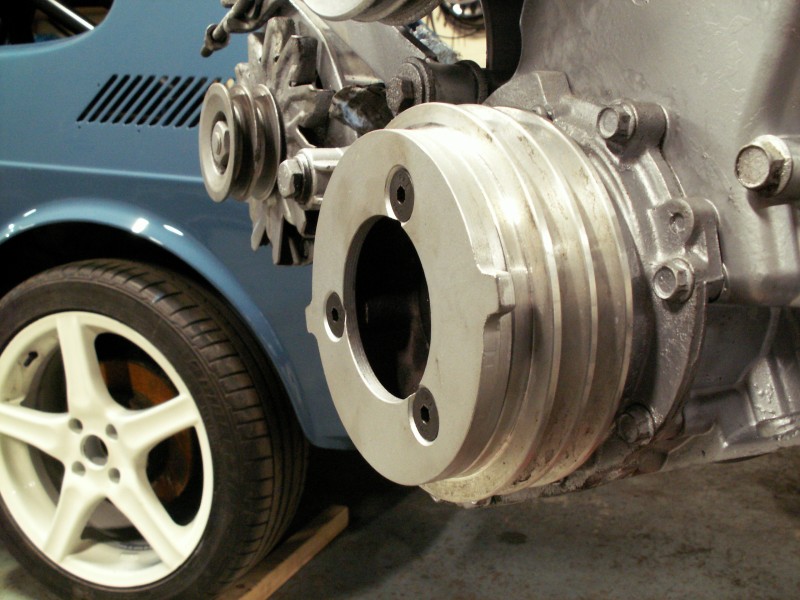
This trigger wheel (2 teeth on iron/steel disc)is in use, works fine.
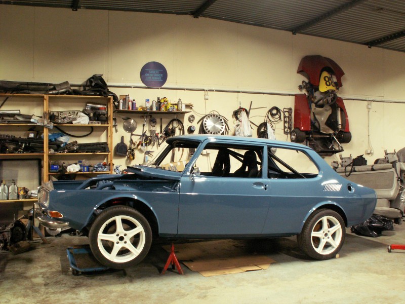
Here is the car, work in progress, just painted after all body and chassis work: