AVR boot code how to
Due to a failure with the electrical system in the car last year, we had to replace the AVR, the new chip was missing a boot loader so this page is about what I did to program the AVR.
( Guidelines copied from MembersPage/SteinOvePrestmo/MyNotes )
The tool used was avrdude which can be found here:
http://www.bsdhome.com/avrdude/
Contents of avrdude.conf file:\n˙1˙
The boot loader hex file was swiped from an old firmware that was compilable (no WBO2 code removed, etc).\n
D:\VEMS>avrdude -c bsd -p m128 -U flash:w:main.hex

avrdude: AVR device initialized and ready to accept instructions

Reading | ################################################## | 100% 0.00s

avrdude: Device signature = 0x1e9702


avrdude: NOTE: FLASH memory has been specified, an erase cycle will be performed

         To disable this feature, specify the -D option.
avrdude: erasing chip
avrdude: reading input file "main.hex"
avrdude: input file main.hex auto detected as Intel Hex
avrdude: writing flash (131072 bytes):

Writing | ################################################## | 100% 50.61s

avrdude: 131072 bytes of flash written
avrdude: verifying flash memory against main.hex:
avrdude: load data flash data from input file main.hex:
avrdude: input file main.hex auto detected as Intel Hex
avrdude: input file main.hex contains 131072 bytes
avrdude: reading on-chip flash data:

Reading | ################################################## | 100% 48.36s

avrdude: verifying ...
avrdude: 131072 bytes of flash verified

avrdude: safemode: Fuses OK

avrdude done.  Thank you.
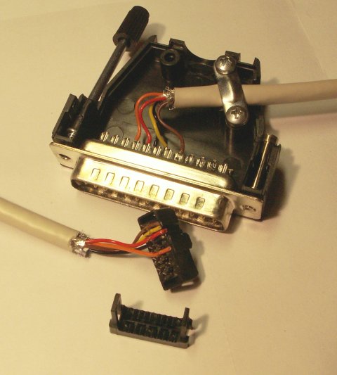
This cable is to be used togheter with the "-C bsd" command in AVRDUDE
| AVR pin command | ISP header # | Parallel port pin | Notes |
| AVR /RESET | 5 | 7 | Yellow |
| AVR SCK (clock input) | 3 | 8 | Black |
| AVR PDI (RXD) (instruction in) | 4 | 9 | Red |
| AVR PDO (TXD) (data out) | 1 | 10 | Orange |
| Signal Ground | 6 | 18 | Brown |
Correct pins from the schematics AVR pin 2 = RXD/PDI -> ISP header Pin4, AVR Pin3 = TXD/PDO -> ISP header pin 1
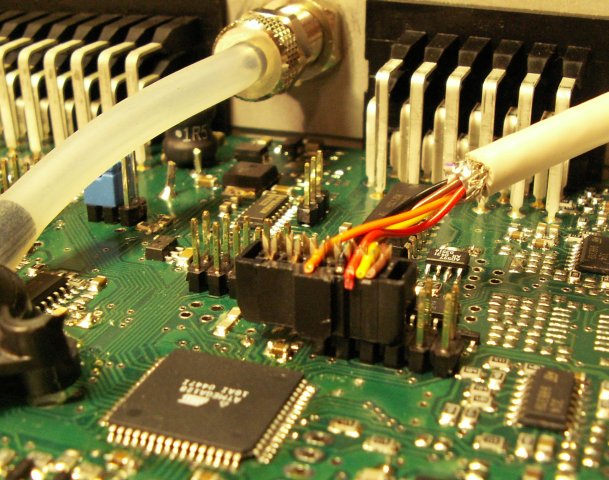
This is what it looked like: