Update: Engine is running. I had to rotate the ignition outputs.
NEW Order: h[2]=10 76 60 30 20 50 50 50
'''In MT = 2-3-6-7-1 (bottom to top)
OLD Order: h[2]=76 60 30 20 10 50 50 50
'''In MT = 1-2-3-6-7 (bottom to top)
'''I assume this is because of the secondary trigger placement.
Can someone check the rest of the config to make sure it is correct for a 3B engine?'''
OLD dumps below - secondary trigger was "disabled" in MT(fixed)
http://www.vems.hu/files/KevinBlack/CGFinalBaseDump.rtf
Datalog - shows 3 ECU Resets, 2 PW drops to zero at idle, and one trigger error
http://www.vems.hu/files/KevinBlack/Cg%20Drive%201.xls
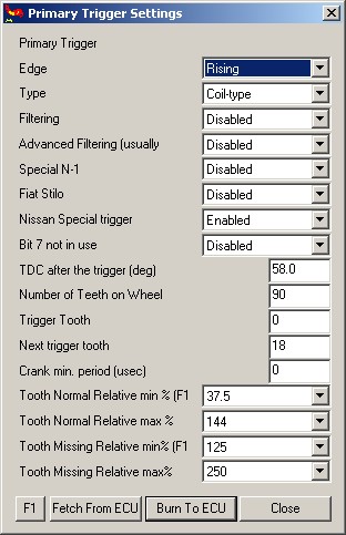
Primary Trigger Settings, note no "crankminper" setting, does this explain the trigger error? (should be ~2600 for 8000+100 rpm limit)
- What about the "Nissan Trigger enabled?
Ignition Configuration / Wiring, 5 IGBT Outputs
IGN Output - EC36 - Color - Cylinder
10 - 33 - Blue(Tape) - Cyl 1
20 - 34 - Black - Cyl 2
30 - 36 - Brown - Cyl 4
60 - 24 - Red - Cyl 5
70 - 10 - Blue - Cyl 3
Firing Order 1-2-4-5-3
Car Information:
- 1991 Audi 200 20vtq,(3B)
- Stock injectors, 3.5 bar fuel pressure
- 5 individual 12V power coils
ECU information
- Webshop assembled Serial # 2016
- 1.1.27 Firmware
- Marcell config and tables for 3B
- Megatune 1.1.23 and or V3GUI for tuning
Questions:
- Does 3B Engine need crankhome wires reversed?
- yes
- Done - Black crank-home connector Pin1=Red to ECU 48, Pin 2=Violet to ECU 49
- yes
- What is Cam Hall inversion?
- a small (NPN) inverter inside the box makes low/hi from hi/low input (on EC36/13)
- Need to check config (Marcells config shows 90 tooth for trigger? I thought it is 135 tooth?)
- actually 270 tooth, so 90 because of the divby3
- Need to verify all trigger functions - shipping this ecu to a customer
- you can use soundcard, left channel to EC36/27, right channel to EC18/12. Use c270 trigger
- Need documentation about how P259, INJ, etc. is wired to Motronic55 connector
- See the 3B column in the spreadsheet. http://vems.hu/download/v3/Motronic55/motronic-AAN-ECxx.xls
- also see the functions in the config. Eg p259/0 (ec36/4) is tach out.
- also keep track of what you ordered. The SSC6 pinout can vary according to customer request (pins can be analog input, or ignout logiclevel/power ign out, or gnd)
Requested Configuration
MAP connection 400kPa onboard - brass nipple
Flyback - 30v Diode
LCD - Connector through endplate (DSUB9 on endplate or flying loom)
EGT - Flying Loom through endplate
Knock - Via Motronic55 Pins
IAT - Audi PTC Sensor (430 Ohm pull-up)
Ignition Configuration, 5 IGBT Outputs
IGN Output - EC36 - Color - Cylinder
10 - 33 - Blue(Tape) - Cyl 1
20 - 34 - Black - Cyl 2
30 - 36 - Brown - Cyl 4
60 - 24 - Red - Cyl 5
70 - 10 - Blue - Cyl 3
Firing Order 1-2-4-5-3
2 Analog Inputs, custom connector
- Red (Analog 7) 8,400 Ohms to Pin 12 5V
- Blue(Analog 6) 8,400 Ohms to Pin 12 5V
Launch Control and Shift Cut Setup
- How do I wire and set-up the Launch/Shift as described below?
As you see, the "AAN ECU extra connector pins" has 3 analog inputs, we use one brake-light switch mounted under clutch (and a series switch that can disable it) to pull down (activate) the (shared) input for shiftcut and launch.
When activated with TPS < iac_tps_threshold launch is activated (TPS can be pressed after activation). Otherwise shiftcut is activated.
WBO2 Configuration
SSC Pin - Flying Lead - WB02 Pin
- 1,black Nernst,WBO2 Pin 1
- 2,White +12V (motronic pin27) 3
- 3,Grey Heater(-),WBO2 Pin 4
- 4,transparent Pump(-),WBO2 Pin 5
- 5,thin red Pump(+),WBO2 Pin 6
Suggestion - make WBO2 wire colors match the LSU4.2 sensor
SSC - Color - WBO2 Pin
- 1 - Black - 1
- 2 - Grey - 3
- 3 - White - 4
- 4 - Yellow - 5
- 5 - Red - 6
General Audi Information
Pic of ECU Connector:
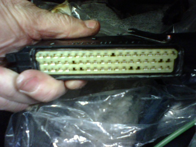
3B Wiring Pinout:
http://www.s2central.net/motronic_pinout_3B.html
3B Wiring Schematic:

Audi 3B Information:
http://www.s2central.net/motronic_02.html
http://www.sjmautotechnik.com/trouble_shooting/20vboost.html