Date: 25.04.2018.
KTM 250 RC
Startup setup:
| Plug type: EC36 | ||
| Pin no. | Pin’s name | Pin’s connection |
| 1 | TPS IN | Throttle position sensor |
| 2 | IAT IN | Intake air temperature sensor |
| 3 | P259 ch.4 | Low current output (350 mA), relay control, etc. |
| 4 | P259 ch.0 | Low current output (350 mA), relay control, etc. |
| 5 | GND | Ground |
| 6 | Injectpr G ch. 64 | Gives signal to an injector |
| 7 | Injector A ch. 1 | Gives signal to an injector |
| 8 | Injector E ch. 64 | Gives signal to an injector |
| 9 | Injector E ch. 16 | Gives signal to an injector |
| 10 | Ignition output 07 | Gives ignition signal |
| 11 | Ignition output 04 | Gives ignition signal |
| 12 | Ignition output 05 | Gives ignition signal |
| 13 | Secondary trigger (CAM) | Unused pin |
| 14 | CLT | Coolant temperature |
| 15 | Fuel relay (P259 ch.5) | Fuel pump relay |
| 16 | P259 ch.1 | Low current output (350 mA), relay control, etc. |
| 17 | Injector H ch. 128 | Gives signal to an injector |
| 18 | Injector F ch. 32 | Gives signal to an injector |
| 19 | Injector B ch.2 | Gives signal to an injector |
| 20 | Injector D ch. 8 | Gives signal to an injector |
| 21 | GND | Ground |
| 22 | GND | Ground |
| 23 | Flyback (to injector) | HIGH-Z flyback diode for the injector (40V) |
| 24 | Ignition output 06 | Gives ignition signal |
| 25 | 12V from battery | +12V battery source |
| 26 | GND | Ground |
| 27 | Primary trigger (CKP) | Crankshaft sensor |
| 28 | +5V battery | +5V battery source for the sensors |
| 29 | TPS battery | Battery source for the throttle position sensor |
| 30 | C259 ch. 7 | Low current output (350 mA), relay control, etc. |
| 31 | P259 ch. 6 | Low current output (350 mA), relay control, etc. |
| 32 | GND | Ground |
| 33 | Ignition output 01 | Gives ignition signal |
| 34 | Ignition output 02 | Gives ignition signal |
| 35 | Ignition output 00 | Gives ignition signal |
| 36 | Ignition output 02 | Gives ignition signal |
| Plug type: EC18 | ||
| Pin no. | Pin’s name | Pin’s connection |
| 1 | Analog ch. 0/Knock 1 (depends on specification) | Unused pin / knock sensor can be connected to it |
| 2 | Analaog ch. 5 | |
| 3 | Analaog ch. 2 | |
| 4 | Stepper A | IACV |
| 5 | Stepper C | IACV |
| 6 | Analog ch. 6/MAP IN (depends on specification) | Manifold pressure sensor/measures intake pressure |
| 7 | WBO2 pump negative (-) | LSU 4.9 pin 5 |
| 8 | Wheel speed input | |
| 9 | WBO2 pump positive (+) | LSU 4.9 pin 6 |
| 10 | Stepper D | IACV |
| 11 | Stepper B | IACV |
| 12 | Analog ch.7/secondary VR (depends on specification) | Unused pin/secondary crankshaft sensor can be installed |
| 13 | WBO2 nerst signal | LSU 4.9 pin 1 |
| 14 | RS232 DSUB pin 3 | Peripherial port (it is needed for computer connection) |
| 15 | RS232 DSUB pin 2 | Peripherial port (it is needed for computer connection) |
| 16 | Analog ch. 1/1-wire interface (depends on specification) | unused pin |
| 17 | GND | Ground |
| 18 | WBO2 heater | LSU 4.9 pin 4 |
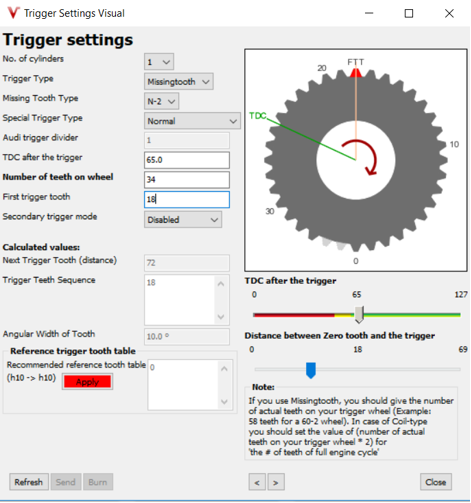
A picture of trigger settings:
[
We will use the VEMS V3 ECU.
The engine’s specifications:
| Combustion | 4 stroke internal combustion |
| Number of cylinders | 1 |
| Valves | Double overhead camshafts, 4 valves per cylinder |
| Cooling | Liquid-cooled, permanent circulation of coolant by water pump |
| Engine displacement | 248.8 cm3 |
| Bore x stroke | 72 x 61.1 mm |
| Compression ratio | 12.5/1 |
| Lubrication | Wet sump |
| Intake valve diameter | 29 mm |
| Exhaust valve diameter | 24 mm |
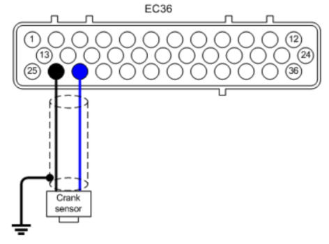
Crankshaft position sensor wiring (VR sensor)
In the engineblock, on the flywheel there are 36-32 teeth. It comes with a VR sensor from the factory. That is what we are going to use.
Wiring it up to the VEMS:
- EC36-pin27 VR (+) (central wire in coax)
- EC36-pin26 VR (-) (shield and ground)
(The shield mus be grounded to the motorblock near the VR sensor.)
Inlet air temperature sensor (IAT/MAT):
Wiring:
- EC36-pin2 Signal
- EC36-pin26 Ground
Coolant temperature sensor (CLT):
Wiring:
- EC36-pin14 Signal
- EC36-pin26 Ground
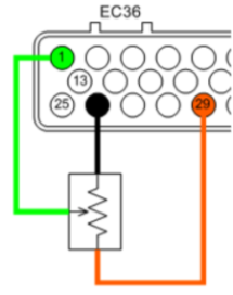
TPS:
Wiring:
- EC36-pin29 TPS (+5V) out
- EC36-pin1 Wiper out (0-5V)
- EC36-pin26 Ground
Edge(s) For Sensor
The setting is typically "rising". "Both edges" results in (2x) higher reading but only works with very precise signal with exactly 50% duty (not needed for any known setup; might be dropped in future)
"Sensor signal min length" (speed_min_time, 64 usec resolution)
0: disables filtering. NonZero: pulses closer than this (64-16320 usec) are dropped (considered noise).
Speed Sensor Calibration
Enter the frequency of your sensor at 100 km/h (or 100 mph if mph reading is desired). 0: disable speed input (after reenable+burn: reboot ECU to start sensing).
Speed Sensor divider
Divide the sensor frequency by this value.
Example:
Edge(s) For Sensor = rising
k = number of wheel sensor pulses per rotation
f = frequency of the sensor
d = wheel diameter
v = velocity of the vehicle
(d⋅π⋅f)/k=v
v= 100km/h = 27.77m/s (alternatively for 100 mph: 44.7 m/s)
d= 0.6m
k= 10
f=147.3Hz
then frequency of your sensor at 100 km/h = 147Hz
Second wheelspeed sensor calibration = 1 is special: wheelspeed2 pulses will be used for sectrig position measurement. Useful for subaru 4 trigger system. DO NOT configure 2nd wheelspeed sensor calibration = 1 if not having 4th trigger sensor. Value=0 to disable, or actual calibration (2-255) if using 2nd wheelspeed input as wheelspeed input (frequency measurement).
Gear Detection Settings (based on first speed sensor)
Enter your speed for each gear at 5000 rpm.
If Shiftcut input is chosen for drum position sensor, each gear is defined by voltage for each gear, and shift cut thresholds is based on the difference from these voltages. The table for this is found under Motorsports menu.