My flyback page
Original problem:
I cannot get stable idle and low load (<2500rpm) area using lambda values above 0.9. Actually I need to use 0.85-0.88 on these areas. This engine is happy to operate on 1-1.05 lambda with stock (injector, ecu, fuel) setup.
Original setup:
BMW M30B34 turbo engine, 1200cc low-Z (2.0 Ohm) injectors with E85 fuel. In-line resistors from webshop and 30V transient flyback diode.
Experiment #1:
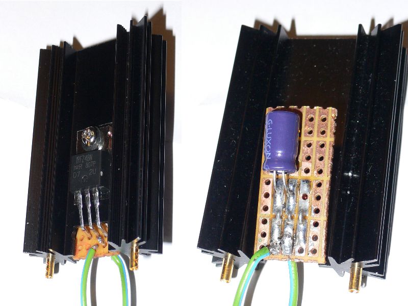
Just tried alternative flyback from MembersPage/GintsK/FlybackForLowZ
- I've got slightly faster closing than 30V zener setup (my idle lambda changed from ~0.9 to ~0.94), with resistors still inline. Note that effective flyback voltage also rose from 30V to 36V.
Experiment #2:
Resistors removed and changed to pwm mode (still high voltage flyback -> explicitely forbidden combination). It was very sensitive to pwm duty %, in fact I couldn't get stable opening below 75% duty. This way low load lambda control results was better, actually I set VE to lambda=~1 values on low load which was original goal. On high load this high duty pwm fried one of my injectors. (10A fuse still intact)
Update: INJD output is dead (always on, measuring 8 Ohms to ground with ECU disconnected). Probably it is the cause of frying injector #4 while other ones had no problem.
Update2: injFET death confirmed, killed another two with a healthy push off throttle. (This time with 2A fuses per channel, both of them blown -after the FETs died). I guess not current but voltage peak reaches the fet(?)
This is my third time of dying injector outputs. High voltage flyback and PWM-ing has been explicitely forbidden from the very start. We need to sort out possible causes because it's really annoying and dangerous.
My observations show that going to 36V switched flyback will accelerate closing of injectors significantly, and omitting inline resistors will accelerate opening of injectors also.
As it seems these injectors cannot handle this high current load, I thought abut some sort of switching flyback.
Switching flyback strategy #1:
No inline resistors, PWM mode, low voltage AND high voltage flyback switched by per-channel flyback logic. Low voltage flyback during the pwm phase and high voltage flyback switched immediately after closing. (64us?)
Switching flyback strategy #2:
Inline resistors, no PWM mode, high voltage flyback.
On injector opening switching logic switches a direct connection between FET and injectors (avoiding inline resistors).
After ~1ms it switches off, so resistors will limit current afterwards.
Pulling injector to higher than GND5 after the peak period
As high voltage flyback is essential with big injectors, there is a solution that can be better than PWM-ing (with only marginally higher component-count):
- Making a VBATT-3V rail (eg. sg3524 bipolar transistor driver or uc3825 FETdriver chip), and using 2 FETs per injector.
- Pulling to GND5 for 1msec (injector peak time)
- and pulling to VBATT-3V rail for the rest of the injection pulsewidth. (a diode is needed in this branch to prevent the FET drain going negative in the first 1msec).
- without PWM-ing the injector pulsewidth gets slightly more precise at low pulsewidth (especially 1 .. 1.9 msec). Good for a high-power streetcar without injector staging
Interesting idea, probably It would need much less energy to hold (based on my current pwm duty).
- probably pulling to 9V would be enough?
- 3..5V across the injector keeps injector current around proper "hold" value. Note the specific voltage below VBATT, not above GND. (so say "4.5V below VBATT", not "9V").
- For the low PW area I could set 1.5 or 2ms peak time to get similar results, couldn't I?
- not really. Because higher than 1 msec peak time will also raise injector current, resulting in slower closing => fuel control also harder.
Try this solution(strategt #1)
http://www.vems.hu/wiki/index.php?page=MembersPage%2FDamirMuha%2FLowZinjectorsFlyback
http://www.vems.hu/wiki/index.php?page=MembersPage%2FGoranJurkovic%2FDaewooLaNOS%2FLPG
- I've built this dual-voltage circuit
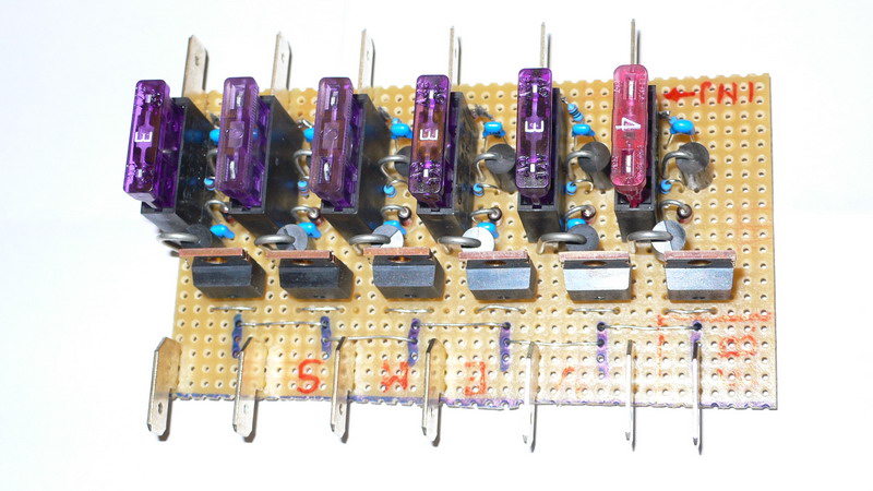
This resulted in reasonable injector control from around 20% pwm duty, and fast opening-closing as before, but in high load area it ended up in death of another two injFETs.
-Good to know that after blowing the fuse it wont blow another one as hot injector's impedance gets much higher and this results in lower current (still enough to burn the injector coil in a minute or two).
I'd really appreciate any ideas...
- I use irf640N mosfet for injectors without heat sink(no heating). It's 200V 18A mosfet so you can use 50V flyback without problems. So far i put them in 7cars and so far not a signel problem.
- Thank you, I was using 1ms and 35% this time. Do you mean to replace all original injfet drivers and install irf640N instead? May I use same mounting and clamping as the originals? -Or just cut it short and no clamping to case at all?
- Originals mosfet have insulated case and irf640N don't. You can clamp to case if you put insulator. I suggest no clamping to case(leave in air).

- Originals mosfet have insulated case and irf640N don't. You can clamp to case if you put insulator. I suggest no clamping to case(leave in air).
- I've installed the new FETs just like the originals were (clamped to housing with silicone insulation sheet). It works fine, no problem with PWM and switched voltage flyback. I'm using 1ms peak and 25% duty. Will going to 36V zeners instead of existing 30V for a little more improvement, but results are far superior to any previous solutions already! Thanks!
2010.02.17. A little update: almost a year has passed (and a few 1000 kms) and no problems to the injector drivers, no blown fuses, no fried injectors, and so on. This injector control method seems to be a very powerful one for my injector set. PWM-noise causes no problem for me.
I've a strange lambda issue however, possibly not injector-control related: Having started the engine and warming-up fully I get nice idle at ~0.95-0.98 lambda. After going 100km, I get much leaner values like 1.05. After cooling the car for a few hours it starts over again.
EGO control disabled, temperatures, RPM, MAP, PW times are similar in logs, fuel pressure seems constant. I don't know what it might be related.
This is not always the case, but summertime it seems tipical.
[dnb] What is the manifold air temperature doing on the runs where you see long term leaning out of the lambda? You may have a heatsoak issue.