There is a contradiction about crank-pattern inside the Subaru manual (thanx for everyone contributing so we finally sorted it)
Cam info
There is a camsync pulse 45 crank degrees before Cyl 1 TDC, then the second comes 135 crank degrees after TDC
Camsync:
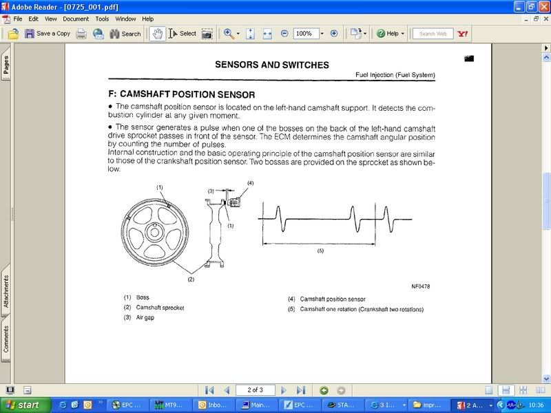
The relative position of the cam (having the camsync pulse coming inside the middle of the long gap) was a reasonable design decision.
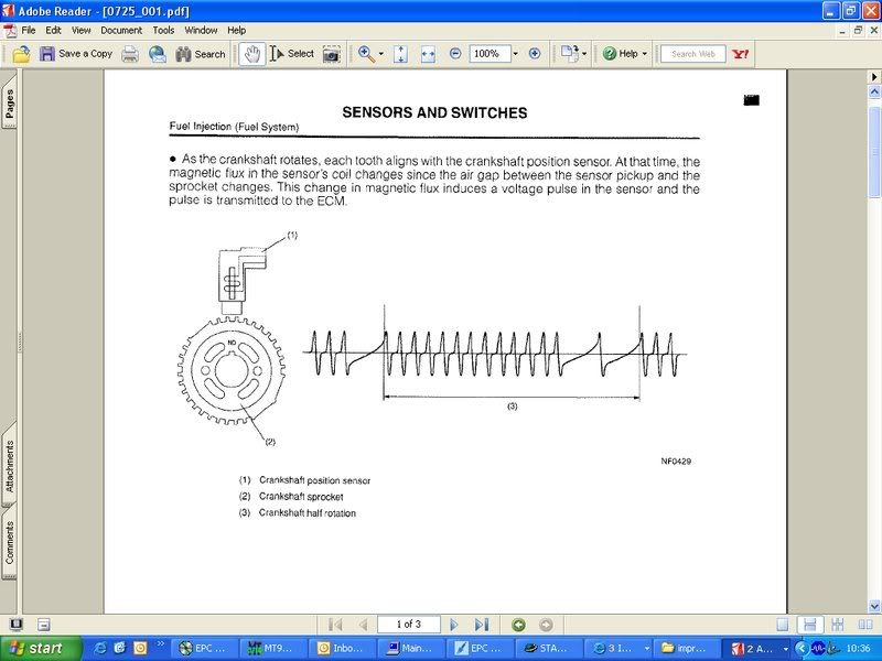
Crank:
- 36-2-2-2 setup: 36 crank teeth
- missing 2 teeth BTDC Cyl 1 (long gap from 60 to 30 BTDC cyl1)
- and 2 teeth twice before BTDC Cyl 3. (long gap from 60 to 30 and 30 to 0 BTDC cyl3)
- Seen on North American 2.2L SOHC plants (99-01 model using 2 teeth cam wheel) as well as other 2.0L/2.5L Turbo plants (most using 4-1 cam wheel) ?????
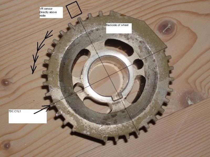
On both pics with the wheel, the wheel turns anti-clockwise. The engine runs clockwise, but the pic is of the back of the wheel.
The engine and the wheel physically turn clockwise, but the above photo shows the back of the wheel, so looking at the pic, the wheel turns counter clockwise.
That confirms: our implementation assumed the above photographed wheel rotates COUNTERCLOCKWISE so the double long gap is followed by 13 tooth, not 16.
Crank Sensor wheel drawing, as mounted on the engine - rotates clockwise: (Beware: the plotted function is wrong: it shows a group of 13 teeth, instead of 16! This caused a lot of confusion)
just thinking
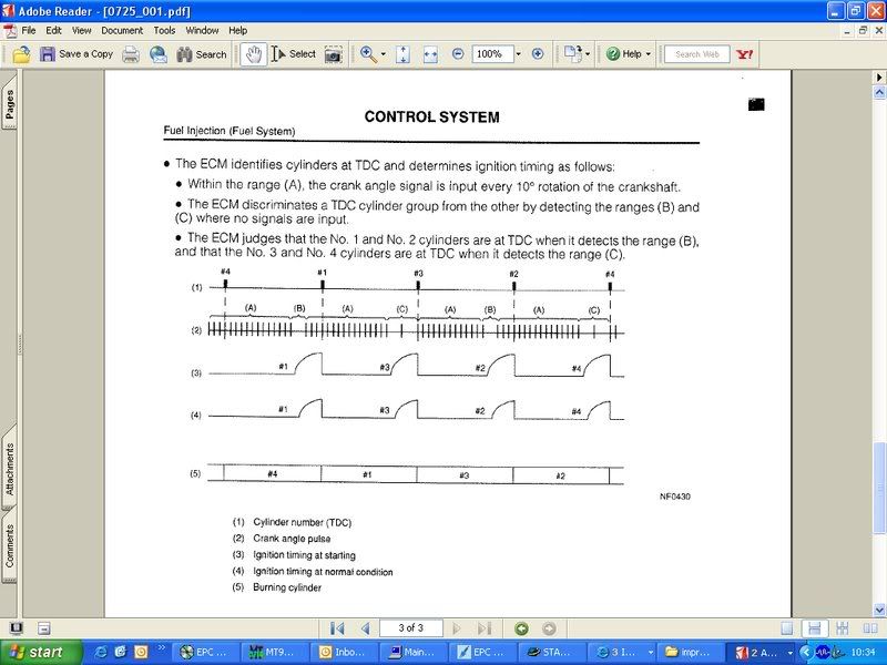
The choice to have the long gap detected at 30 BTDC and 0 TDC is weird.
- for fastest sync during cranking, 40 BTDC and 10 TDC would make most sense.
- for most precise timing during the whole range (and also for programmer's convenience) 90 BTDC and 60 BTDC would make most sense
We can look at it as 15+3,3+12+3
- TDC is 30 crankdegrees after the single missing gap
- in other words, TDC is the 4th tooth after the single long gap
Subaru 36-2-2-2 implemented with camsync: derived from c024 (12 cranktooth + 1 campulse)
- date:17-december-2010:IS the 36-2-2-2 working without camsync?,1.1.81 as i still have some problems with 6/7, and would the change the crankwheel?/Skassa
- Date: 22-March-2011, Yes, I ran the engine upon first startup with dualout and no camsync. Then a few minutes later changed it to camsync and sequential.
- |http://www.vems.hu/download/v3/firmware/experimental/ 1.1.76 experimental] works
- 1.1.78 will be modified and tested later
- start from a sane config, than at the bottom of primary trigger dialog click the subaru configlet (so primtrig subaru mode), than change:
- nr of tooth on wheel = 24 (yes, 2*12, not 30 !)
- tooth width = 30 degree (=3 * normal tooth)
- another_trigger_tooth=6 if 4 cyl
- (3 if 8 cyl, but assuming 4 cyl here)
- reference tooth from top to bottom: 0 18 12 6 ...
- optional: disable camsync.
- But beware: it is ment to work with camsync. Might or might not be possible to set up to operate without camsync. With COPs, use camsync as ign-dualout overloads COP ignition coils easily.
Than burn, and might need to reboot.
Please measure+figure how to set trigger tooth and TDCdelay.
(tooth 0 is after the long gap after the group of 16 normal tooth). So triggertooth=4 + 90 deg TDC-delay or triggertooth=5 + 60 deg TDC-delay SEEMS appropriate. (The strobe will tell)
Test pattern - codenamed "s362" in wav filenames and signalgenerators
Here is a [wav file] (with CamSync. Inverted to play properly. 735 RPM)
- this wav does not match the above spec
- the campulse comes in the first long gap, not the second. But it changes even within the file. The first crank rotation was good. The second crank rotation had the wrong number of teeth after the double gap. A cut and paste error.
- Note the wheels in the above photo rotate anti-clockwise since looking at the back. The drawn wheel turns clockwise. The wrong time-line in the subaru manual next to the wheel drawing was the cause of the confusion.
- So 16 pulses, gap, tooth 0, another gap, 13 pulses, gap, and it restarts
- verify any pattern (not just the first cycle), and reverse in time if necessary, also invert in audacity if needed.
- Than sectrig-triggerlog showed pulsetrain is reasonable for some testing.
- 2010-06-16 and newer VT also plays 36-2-2-2 in "Tools/Play Trigger" if s362 type is typed in the combo
- the campulse comes in the first long gap, not the second. But it changes even within the file. The first crank rotation was good. The second crank rotation had the wrong number of teeth after the double gap. A cut and paste error.
Testing - some [configs] that were used for testing
Since the 2010-06-15 experimental 1.1.76 seems to act properly (36-2-2-2 with camsync or with subaru 6+7 with camsync). Can be tried on bench or engine.
- 1.1.78 (since 2010-06-18 experimental) seems to act well on s362 (36-2-2-2 with camsync also with subaru 6+7 with camsync). Subaru code is basically same as in 1.1.76. Test on bench first, if you intend to use this. (and remember to review all the new settings like per cylinder ign-delay and fuel-pw-adjustments)
Jason's notes
- Jason can get it to trigger with camsync disabled, and can enable camsync and the rpm becomes closer, but trigg errors. If you stop stim signal it will not register rpm again with camsync enabled.
Here is a [vemscfg file] of the setup described above (trigger settings)
In Jason's engine there is the possibility of using a 4-1 cam signal. It's for the 2004 WRX STi variable cam system (disabled on this engine for now) and those sensors are still there but unused. We should figure out the 2 pulse camsync, but if the 4-1 is easier to handle quickly, I'm ok with that. There is a 4-1 on each cam, but I expect it's sufficient to just read one of the two (just like this 2 pulse cam trigger).
- from 1.1.92 VVT has special firmware support, the OLD Subaru implemetation changed,
- trigger event is the first pulse after the double missing if the cam trigger received in the tooth detect zone
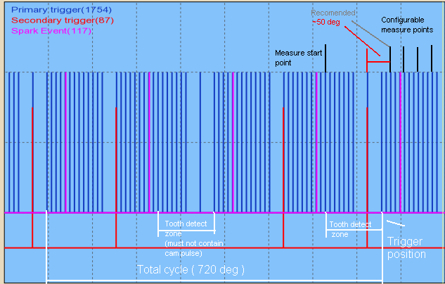
- VVT measures from the trigger cam tooth to the configured measure tooth ( default = 3 )
Assuming that is the most retarded position. (correct ?)
link to a site, were there is crank 36-2-2-2, plus cam 4-1,
http://www.msextra.com/forums/viewtopic.php?f=131&t=36430
this is what there is on the subaru´s when the run inlet avcs, so NOT 36-2-2-2 and the 2pulse cam wheel
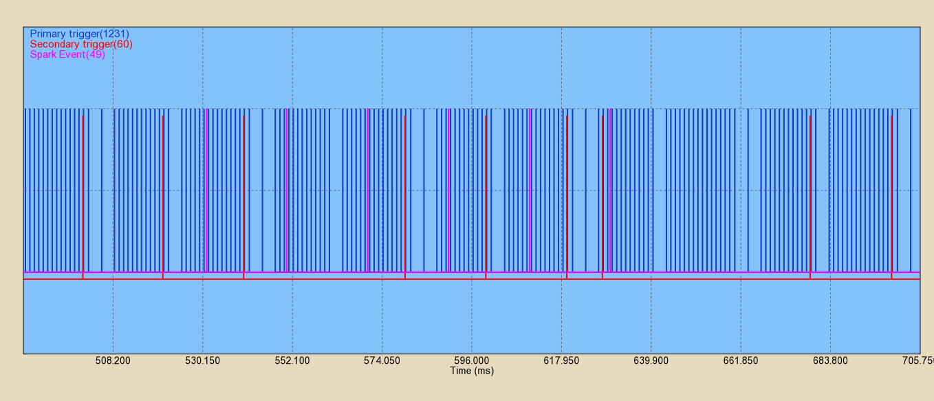
A triggerlog, where
- apparently B is connected (not A). B would require different config (derived from the suzuki setup), so connect A to sectrig if possible.
- also, there is an offending extra pulse !
- maybe because VR input is used with a HALL input ?
- we need to find the cause of this pulse to cure the no-sync problem (otherwise the primtrig is detected and RPM seems correct)
Camshaft-angle control
Firmware originally supported camshaft-angle control with missing tooth primary trigger. But someone on irc requested 36-2-2-2 (without writing details here or there).
We added firmware support for 36-2-2-2 (with the factory 2-pulse camsync) camshaft angle control (1.1.82), but there are still open questions...
- upto 2008 only intake cam is with avcs(vvt)
- exhaust cam is not controlled
- good, because now the special 2-pulse campattern is supported for intake cam only (only the normal 1-pulse campattern is supported for the exhaust cam).
- the max possible crankadvance is 46degrees(23degrees cam)
Engine has 2 VR + 2 cam-HALL sensors in total:
- 36-2-2-2 on crank
- 2 cam-HALL sensors(this is only tru on US model), others run VR as previus stated!!: 4-1 pattern (see pic above) on right and left inletcam, at the back of the cam (for cam position feedback)
- 2 pulse camsync (secondary vr on left camwheel)
- this is constant position, does not change when the cam PWM solenoids are actuated, right ?
- yes this was used for camsync and is constant, I believe the second trigger is a leftover from engines not running avcs,as this have also been removed from the later engines,that all run avcs,the new engines only run the cranktrigger, and the 2feedback sensores on the right and left cam
- please confirm that this is not needed when setup for camshaft-angle control (probably used as backup in the factory setup, maybe to better tolerate loss of cranksensor signal ?)
- Yep, not needed
- this is constant position, does not change when the cam PWM solenoids are actuated, right ?
Trigger inputs - 3 should be enough
- 2 onboard (primary+secondary trigger)
- and one external [DSUB9 VR to HALL] is not needed because cam sensors are HALL!
- this 3d can be connected to the 2nd cam-input, traditionally called "exhaust cam input" - even if it's not exhaust cam in this application. (and at least 1 wheelspeed is still available)
- but the special pulsetrain must be implemented for the "exhaust cam".
Output solenoids ?
- 2 solenoids (both are PWM) one on the left side and one on the right side