Changes by last author:
Added:
|
Purchase, assembly, setup, and installation
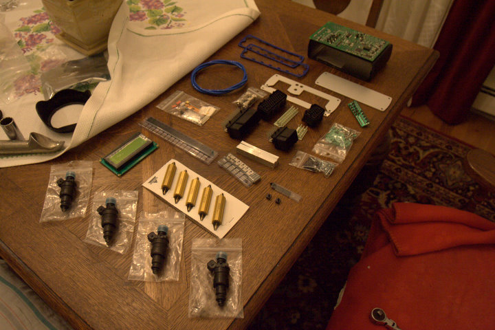
---- Purchase On Sept. 25, 2008 I purchased the following items: VEMS shop: *GenBoard v3.3 *Power Flyback - With wire yes *Econoseal36-PCB *Econoseal18-PCB *EconoSeal36-Wire side *Econoseal18-Wire side *Alubos EC frontplate - Drill-count 3 small *Alubos Endplate - Drill-count 4 *Alubos1600 - Drill-count 6 *Ignition driver insulator - Size 2lines *Pneumatic tube *Pneumatic connector *VEMS sticker - Color 9-pack Newark and/or Mouser: *IRGB14C40LPBF - Ignition driver FET, 3pcs (2 for board, 1 spare) *MPXH6400AC6U - 400kpa MAP sensor, 2pcs (1 for MAP, 1 for exhaust backpressure) *RH0506R000FE02 - 6R 50W power resistor, 5pcs *FQPF20N06L - Injector driver, 10pcs (8 for board, 2 for wideband heating) *TPIC8101DW - Knock sensor interface, 1pcs A 20x4 HD44780 LCD was also purchased from SparkFun.com
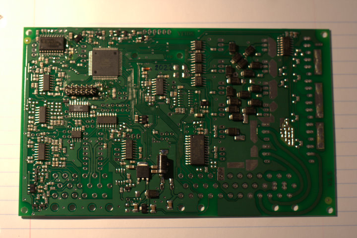
---- Assembly Started with a bare board:
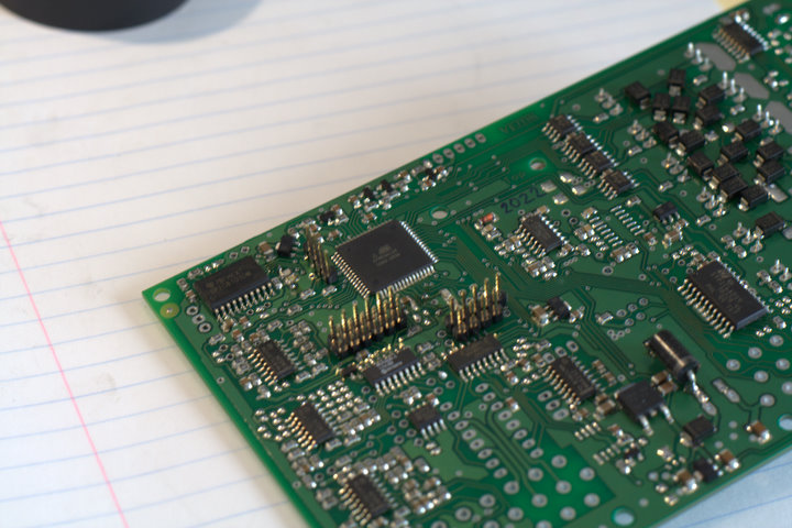
I marked all the IGBT and FET locations: Added the LCD and the PS2 pin headers (these headers are not included, you must supply your own):
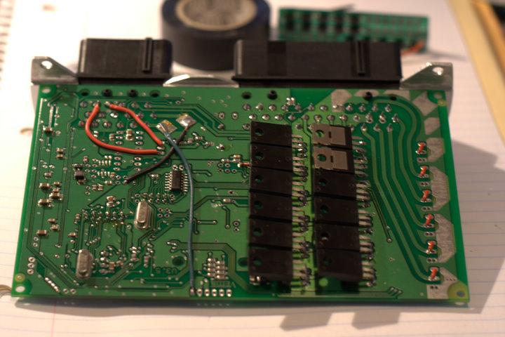
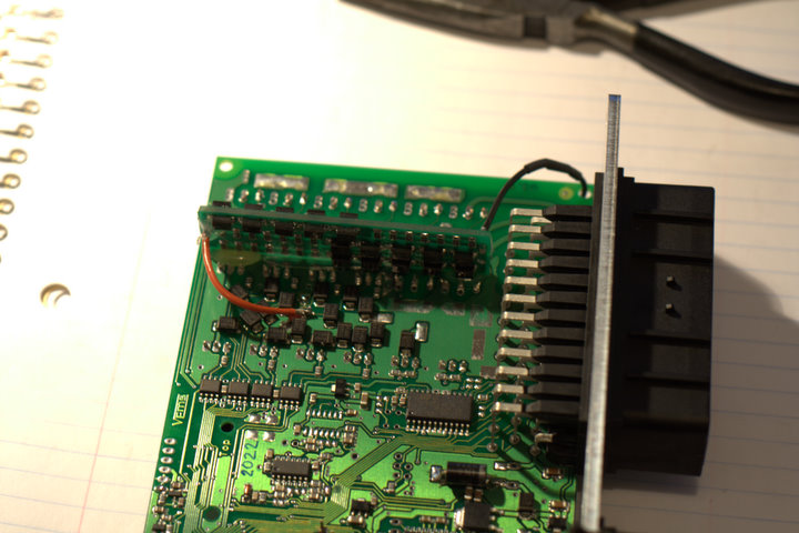
Installed ECM frontplate, EconoSeal connectors, eight injector FETs, two wideband heater FETs, two ignition IGBTs, logic level ignition output jumpers (6 short red wires to the right), RS232 jumpers (two red wires to the left), trigger selection jumper (black), and an external MAP sensor jumper (green, which was later removed in favor of an internal MAP sensor):
At this point I also set up the board for VR primary trigger and Hall secondary trigger. Power flyback (secured with hot glue):
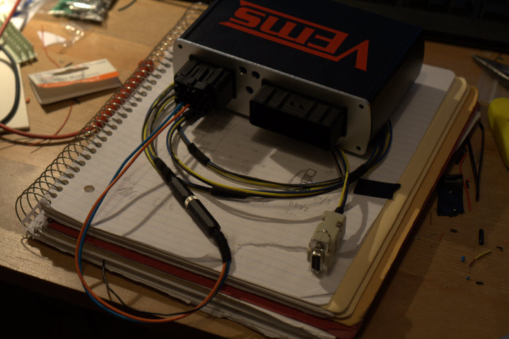
Tuning cable:
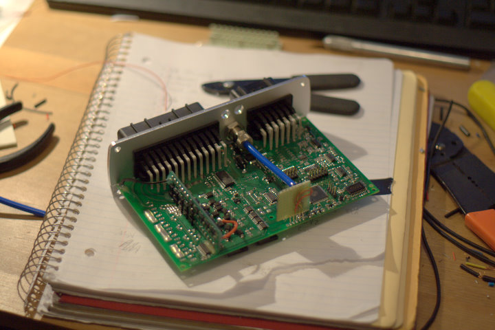
Internal 400kpa MAP sensor (The sensor body was attached to the proto board with hot glue and wired according to the reference circuit shown in the MPXH6400AC6U data sheet):
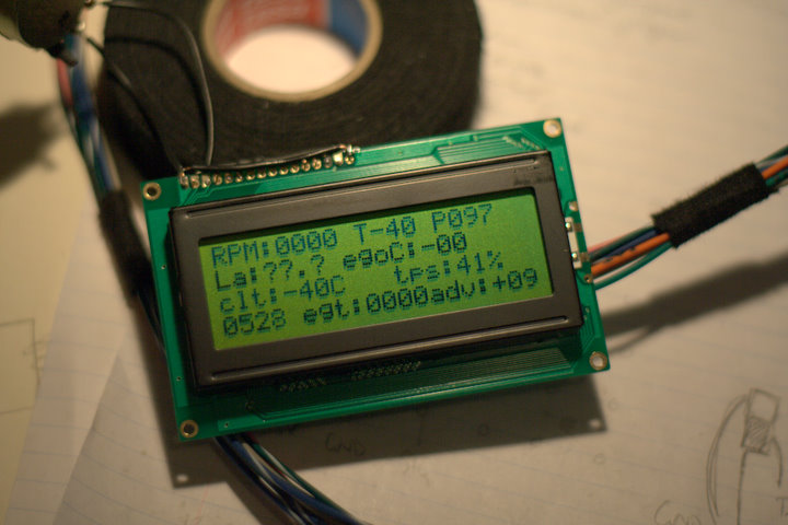
At this point I was ready to plug the board in for the first time. I added the ground re-inforcement wire as per the assembly instructions and connected the grounds as per PhatBob's UserGuide. All the voltages checked out so I moved on to the bootloader flashing. After making an ISP cable I followed Mattias Sandgren's excellent guide here: MembersPage/MattiasSandgren/NickesBMW/AvrBootCode For the firmware flash I followed another excellent guide written by Johan Eriksson: MembersPage/JohanEriksson/VerThreeFirmForDummies LCD installed and tested:
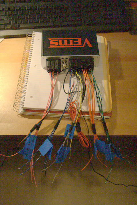
Flying lead harness, all wires color coded by function:
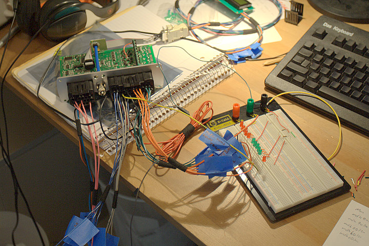
Bench testing the spark, fuel, and fuel pump trigger outputs:
---- After spending three days making the harness and troubleshooting various issues (will elaborate) I finally got the car running. Video: http://www.youtube.com/watch?v=yeMA3r5rOQM On my old MegaSquirt setup I could never get a reliable idle under 800rpm. The ~650rpm idle seen in the video is on a completely untuned warmup cycle and my old MS fuel map. Things are looking good! |
![[1]](http://www.vems.hu/files/MembersPage/KarlBuchka/Assembly/IMG_1937.jpg)