The LCD option is a very useful addition to your Genboard module. With the use of an IBM PC keyboard it becomes invaluable as you will be able to configure your system without having to use a laptop. In the first instance it will provide a method of checking that your VEMS system is working.
| Page | Description |
|---|---|
| 00 | mlp00: Basic engine variables. RPM, injector pulsewidth, Lambda, EGT, throttle position, etc. |
| 01 | mlp01: Basic engine variables with error and other counters. |
| 02 | mlp02: |
| 03 | mlp03: IAC information. |
| 04 | mlp04: VE learn information. |
| 05 | mlp05: Ignition and knock. |
| 06 | mlp06: Alien ignition advance/dwell |
| 07 | mlp07: WBO2 information. |
| 08 | mlp08: EGT information. |
| 09 | mlp09 |
Table 8.1. LCD page descriptions
Please note that the following information assumes that you are using the LCD supplied from the VEMS Webstore. For contrast adjustment, a 2,4K ohm resistor can be connected between connected between LCD-J1 and LCD-J3. The backlight feature is available by inserting a 27 ohm resister between LCD-J15 and LCD-J2. The backlight feature can be switched on or off by using a switch between LCD-J16 and LCD-J1.
The brightness and contrast can be controlled by connecting the following pins.
- LCD-J1 to LCD-J16
- LCD-J1 to LCD-J3 (2,4K ohm resistor)
- LCD-J2 to LCD-J15 (27 ohm resistor)
The LCD must be connected to the Genboard module according to the diagram below.
- LCD-J1 to DSUB9-pin5 GND (brown)
- LCD-J2 to DSUB9-pin1 Vcc (red)
- LCD-J4 to DSUB9-pin9 RS (white)
- LCD-J5 to DSUB9-pin6 R/W (orange)
- LCD-J6 to DSUB9-pin2 Enable (violet)
- LCD-J11 to DSUB9-pin3 Databit4 (green)
- LCD-J12 to DSUB9-pin7 Databit5 (grey)
- LCD-J13 to DSUB9-pin4 Databit6 (blue)
- LCD-J14 to DSUB9-pin8 Databit7 (black)
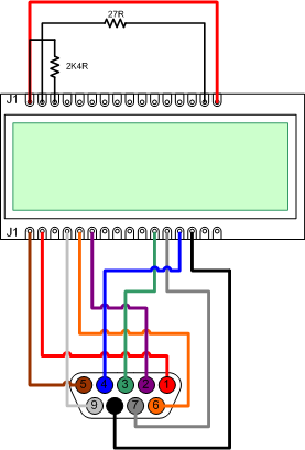
The DSUB9 connector is a female connector.
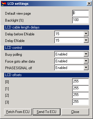
The LCD display is configurable through MegaTune. Normally no configuration is necessary, but parameters should always be checked. Connect the RS232, start MegaTune and power up the Genboard module. Select 'Extras->LCD Settings' in the main menu, the dialog Figure 8.8, “MegaTune - LCD settings” is displayed.
-
Default view page
The option 'Default view page' refers to the different status pages described in Table 8.1, “LCD page descriptions” . Every time the Genboard module is powered up the page configured will be displayed right after the greeting message.
-
Backlight
- TODO
Make sure that the settings match those displayed in Figure 8.8, “MegaTune - LCD settings” and press the 'Send to ECU' button.