Table of Contents
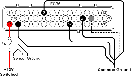
When powering up the Genboard for the first time, it is recommended that the 3A fuse shown in Figure 8.1, “Power wiring diagram” is replaced with a 500mA fast fuse. In case something is wired wrong the small fast fuse might save the Genboard.
First connect the main power supply to the Genboard module.
- EC36-pin25 3A Fused +12v supply
- EC36-pin26 Sensor Ground
ALL grounds must be connected at ALL times! Failing to do so will most certainly damage the Genboard module.
There are two types of ground connections; Sensor Ground and Power Ground. Sensor Grounds are points of common ground for the engine's sensors and must be kept free of the noise generated by injectors and ignition coils. Connect the Sensor Ground to the chassis/engine block or directly to the the battery. Power Grounds are the ground connections for ignition and injector outputs. Power Grounds must always be connected directly to the battery. Power grounds are also called "GND5" grounds in some documents.
The Sensor Ground has many connections (CAS, TPS, IAT, CLT etc). Make provisions for this in your wiring loom.
Power Grounds:
- EC36-pin5
- EC36-pin21
- EC36-pin32
- EC36-pin22 (Installed on all Genboard v3.3 modules, not installed on all v3.0 and v3.2; testing is necessary.)
These must be connected to the battery, preferrably with 3..4 separate wires that meet as close to the battery negative terminal as possible. Failure to do this may result in damage to the Genboard module.
Make sure the Power Ground connections do not break during operation. This is the reason for using separate wires. Even if 1..2 break for some reason, at least 2 remain connected.
Before you put any power through the unit, use a multimeter to ensure the pins are wired correctly.