VEMS v3.3 installation instructions
These instructions are written for a typical Windows Installation. It is important to follow the guide in the defined steps, failure to do this may result in you frying your VEMS module.
In-car installation
Although VEMS has good environmental protection the engine bay of a car is still a very hostile place to install your VEMS module, so its a good idea to follow the lead of most car manufacturers and keep the ECU inside the passenger compartment.
Setting up your PC
The easiest way to configure and tune your VEMS unit is to use a PC, there are a number of tools which will need to be installed before we can start to setup VEMS.
MegaTune package, the latest version of which can be obtained from: http://www.vems.hu/wiki/index.php?page=MegaTune
<<MegaTune, WinTools in here.>>
Step One - Connecting power & testing
The EC36 is the larger Econoseal 36pin plug, and EC18 is the smaller Econoseal plug.
The first thing to do is to get a power supply upto the
- EC36-pin25 3A Fused +12v supply
- EC36-pin26 Signal Ground
NOTE: Signal Ground pin has many connections (CAS, TPS, IAT, CLT ...) make provision for this in your wiring loom.
The 3 Power Grounds (also called as "GND5" in some documents)
- EC36-pin5
- EC36-pin21
- EC36-pin32
- EC36-pin22 this pin is optional, but usually used as an extra GND signal.

Make sure the EC36-pin5 connection does not break during operation. This is the reason for using separate wires: even if 1..2 breaks for some reason (eg. a screw comes loose), at least 2 remains connected.
Before you put any power through the unit use a multimeter to ensure that pins are wired correctly. There is little point in connecting power until the serial connector or LCD screen has been connected.
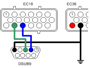
Connecting serial port
To allow the connection of the VEMS unit to your PC a serial port plug must be connected as follows.
- EC18-pin14 to DSUB9-pin3
- EC18-pin15 to DSUB9-pin2
- EC36-pin26 to DSUB9-pin5 (GND).
Testing the VEMS unit
First connect your VEMS serial cable (see Step Two), and make sure that there are no applications that use the serial port running on your PC, applications such as Palm Pilot HotSync.
Connect the EC-18 connector with the serial port to VEMS.
And then connect the EC-36 connector with the power supply.
Navigate to the directory that you installed MegaTune into and double click on the megatune.exe application, and you will be presented with a window:

Select the VEMS Standard 12x12 (Default) option and click OK.

On the Menu bar select Communications->Settings...

Select the com port that VEMS is connected to, and click the 'Click to test' button, if all is well you will see the success message

This shows that your VEMS module is alive and communicating with the PC, close the Settings window and you should see something similar to this:

Close MegaTune and disconnect VEMS from its power supply.
Step Two - Connecting and configuring sensors
Connecting the primary trigger (CAS)
Mechanical considerations (need to be written somewhere and referenced from here)
The VR sensing circuitry is very sensative to electrical noise, sheilded cable (coax) must be used and good grounding is vital.
- EC36-pin27 VR+ (central wire in coax)
- EC36-pin26 VR- (sheild and ground)

Sheilding should be grounded to engine block close to the VR Sensor
Connecting the secondary sensor (optional)
With the same considerations with the primary trigger regarding electrical noise.
- EC36-pin13 VR+ (central wire in coax)
- EC36-pin26 VR- (sheild and ground)

Configuring the system to suit the sensor
[insert config file fragment]
Testing the crank sensor
Use MegaTune. Spin the engine. Watch the rpm value.
What to do if it doesn't work.
Connecting the coolant temp. sensor (CLT)
- EC36-pin14 Signal
- EC36-pin26 Ground (also ground to the engine block close to the sensor)
Connecting the inlet air temp. sensor (IAT)
- EC36-pin2 Signal
- EC36-pin26 Ground (also ground wire to the engine block close to the sensor)
Configuring the temperature sensors
Use EasyTherm to build tables.
Upload tables.
Testing the temperature sensors
Using MegaTune.
Check ambient temperature with thermometer
Check sensors reading on MegaTune or Motuner, compare with thermometer.
Apply known heat (boiling water) and check reading.
Apply known cold (ice) and check reading.
Connecting the throttle position sensor (TPS)
- EC36-pin28 +5v out
- EC36-pin1 Wiper out (0-5v)
- EC36-pin26 Ground (also ground wire to the engine block close to the sensor)
Configuring and testing the TPS
MegaTune TPS setup. Steps and screen shots.
Connecting WBO2 Sensor (optional)
- EC18-pin13 to WB6-pin1 (Nerst Cell Signal)
- EC18-pin7 to WB6-pin5 (WBO2 Pump-)
- EC18-pin18 to WB6-pin4 (WBO2 Heater)
- EC18-pin9 to WB6-pin6 (WBO2 Pump+)
Before we plug the wide band in we need to do some tests and calibration, the first is 'Pump Zero DC', you will need to take a reading with a DVM across pins 5&6 of the Wideband connector. The ideal voltage is zero, to adjust the voltage you will need to change the values of wbo2_pump_pw_zero in config.txt. wbo2_pump_pw_zero value is adjusted during factory test, saved in ECM eeprom. Don't forget to save the output of Manmcd before tinkering with MegaTune or settings. wbo2_pump_pw_zero also written in the WebShop "Sentout" notification email. However, it is recommended to do the test to be sure.
Ideally the value should be between 0x63 to 0x66 (0x64 and 0x65 is most common) and the values make a big difference, for example at 0x65 I measured 0.10v changing to 0x64 resulted in a reading of -0.17 and 0x66 took the reading up to 0.4v. Note that WBO2 must be restarted for the value to take effect (reboot the board, or use mde02mde00 command).
Testing WB02 sensor
Fresh air reading
Configure value to read fresh air O2 level
Connecting exhaust gas temperature sensor (EGT) - Optional
Temp. compensated cable, blah blah blah.
Configuring EGT sensor
Before we can rely on the sensor's readings we need to calibrate VEMS. This is best done using boiling water as we know that at sea-level this boils at 100degreesC. Make sure that the sensor does not touch the sides of the vessel containing the boiling water as this will result in an inaccurate reading. At 100degreesC the voltage fromt the sensor (measured across pins 1&8) should read:4.095mV and AD597's output (pins 4&6) will be 1005mV.
Calibration is required to enable VEMS to display and log the temperature value correctly, there are two values in the Config file that are used to do this:
- egt1_cal=49 # EGT calibration multiplier
- egt1_offs=00 # EGT offset (signed e.g. 0xF0 is -1)
The EGT reading should be on the LCD screen's first page, to show EGT alone you can use Bray terminal to change to page 8 by using the command: Manmde08. Put the first few centimeters of the thermocouple onto some ice and watch the value on the scree drop. Adjust the calibration values until the egt reading is zero.
Testing EGT sensor
Then using a known temperature heat source (like boiling water) to check that the egt value is correct across a wide range.
Connecting manifold air pressure (MAP) sensor
In most cases the MAP sensor is built in to the VEMS module, but it's also possible to use an external sensor if required.
To connect the internal MAP you will need to route some 8mm tubing from the manifold to the VEMS module
Step 3 - Connecting Output Components
VEMS output ports are listed here:
http://www.vems.hu/wiki/index.php?page=GenBoard%2FManual%2FDigitalOut%2FTable <<Remove this link>>
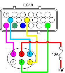
Connecting fuel injectors
VEMS can control anything from 1 to 8 fule injectors individually, although it's also possible to control upto 16 injectors grouped in twos.
IT IS ESSENTIAL that EC36-pin23 is connected to the Injector's common power supply (see diagram), EC36-pin23 controls the voltage spikes that the injectors produce when they close (flyback), failure to connect the flyback pin will fry your VEMS.
- EC18-pin7 to Injector1
- EC18-pin19 to Injector2
- EC18-pin8 to Injector3
- EC18-pin20 to Injector4
- EC18-pin9 to Injector5
- EC18-pin18 to Injector6
- EC18-pin6 to Injector7
- EC18-pin17 to Injector8
This shows the typical installation for a 4 cylinder application.

To 8 injectors are wired as shown here.

And to pair injectors in parallel.

The injector common + signal is connected with a 10A fuse to a switched +12V supply. NOTE the flyback connection is after the fuse.
Connecting ignition components
Single coil
Coil pack
Coil on plug