The ford EDIS is a standalone microprosessor based ignition. It handles all timing calculations and trigger wheel processing internally. Genboard only has to deal with a SAW and PIP signal to make the EDIS setup work.
What happens is the EDIS sends out a PIP signal (falling edge is interesting) that will tell the Genboard module it needs a SAW in return. The length of this SAW signal tells EDIS what timing is desired.
The 8 ignition drivers are composed of a logic level IGBT that supports continuous 14-amps. Ignition coils, DI or DIS, are generally connected with their positive terminal to 12 volts and the negative terminal is connected to the Genboard. These drivers take the negative terminal and connect it to ground when the gate input is triggered.
Help! Where can I find an EDIS module: EDIS 4 is used on:
Sierra 1.8 CVH, toothed wheel is on the back of the crank pulley. Sierra 2.0 Twin cam, both 8 and 16v (pretty certain), toothed wheel is behind the cam belt cover somewhere. Any Mk3/4 Fiesta or Mk4/5 Escort or Mk4/5 Orion or Mk1 Mondeo (only Automatics) with a fuel injected CVH or Zetec engine up to 1995, toothed wheel is part of the flywheel. After 1995 the Edis module was integrated into the main ecu.
I.e Pretty much any fuel injected 4 cylinder Ford between 1990 and 1995 has a EDIS 4 module.
N.B carbed Fords of this sort of age are also distributorless but use a DIS module not a EDIS module, the DIS module is a self contained ignition system, it's not designed to talk to the ECC IV ecu like the EDIS module is and is no use for MSnEDIS.
----
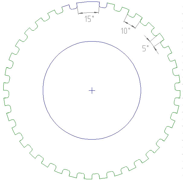
Help! How do I position my sensor/missing tooth?
In short, the position of the wheel relative to the engine isn't directly important. At TDC, the missing tooth should be the correct number of degrees past the VR sensor. This has caused some confusion... heres what I did:-
1. Set the engine to TDC.
2. Fit the VR sensor where it is most convenient for bracketry, wiring etc.
3. Fit the timing wheel with the missing tooth 60deg ahead of the VR sensor (for V6). Since each tooth is 10degrees, I just counted off 6 teeth in the correct direction, and put that tooth directly underneath the sensor.
There is some confusion over Fords wording on the positioning.
"The VRS sensor is located directly opposite the "missing tooth" when cylinder #1 is located at 90 deg BTDC for a 4-cylinder engine, 60 deg BTDC for a 6-cylinder engine and 50 deg BTDC for an 8-cylinder engine, and 36 deg BTDC for a 10-cylinder engine."
It means the sensor should be closest to the missing tooth at this point.
-----
How to determine polarity of VR Sensor
The polarity is important, as I found out the hard way. The sensor will put out a good signal on a scope hooked up either way, but the module won't fire the coil. It is confusing since the wire colors don't seem to match between the module and the sensor.
If you are using a ford harness, the gray wire which comes out of the sensor is the common.
If you don't have a harness, the square side of the sensor body area is the positive side. All other sides are rounded.
You can see VR waveforms from the InputTrigger page. If you want to be absolutely sure, check with scope. With wrong polarity, the output tooth-times (which you can measure with Genboard3.0, probably hard to do with EDIS) after the LM1815 comparator will not be 34*1+2 but 33*1+1.5+1.5
----
Where I can disable EDIS multispark mode? I have this simptoms: (see at the bottom of page)
" Ignition Settings " " unused bits are ignored, but set them high by tradition - eg 11111xxx " " bit2 0:no filtering/1:filtering, bit1 0:toothwheel/1:coil, bit0 0:falling/1:rising" " 0xFE coil type trigger, falling edge (EDIS)" :
primary_trigger=FE
" bit2 0:no filtering/1:filtering, bit1 0:enable/1:disable, bit0 0:falling/1:rising" :
secondary_trigger=FF
" number of teeth on the wheel eg. 0x24 = 36 teeth; not used in case of coil-type trigger"
TODO: explain direct ignition settings, igncount=.. and h[2]=.. and give examples - DummyIgnition page looks good for it
:
tooth_wheel=24
" chose which tooth is the trigger tooth. A value of 00 means the missing tooth will act as the trigger" :
trigger_tooth=00
" Cranktigger period minimum (*16 usec) eg. 0x80 * 16 = 2048uS"
:
crank_minper=80
" TDC after the trigger(0.5crankdeg) eg. 0xFF * 0.5 = 127.5deg"
:
ign_tdcdelay=FF
" dwell length above 14V (64usec) 0x26 * 64 = 2432uS. Only used for dummyignition, since in case of EDIS, the pulselength is the function of the ignition advance"
:
ign_dwell14=26
" added dwell time at 6V (27usec) eg. 0x5A * 27 = 2430uS. This is the slope of the dwell increase, as VBatt decreases. Typical dwell6 time would be: dwell6 = dwell14 * 2"
:
ign_dwell6=5A
" ignition advance at cranking [0.25crankdeg] 0x0F x 0.25 = 3.75deg" :
ign_crank_advance=0F
" ignition type: dummy:70/EDIS:00/none:FF add +01 for inverted output (assuming Genboard v2: inverted means that PORTB7 rising edge is spark, which is falling edge after MISC NPN." :
ign_out=70
" Input Trigger and Ignition Settings "
The first thing that must be configured is the type of trigger(s) that you will be using and how it will behave. The primary and secondary trigger configuration is done with 1-1 hexidecimal number that tells Genboard how to handle the input. As you can see below, you can use input signal filtering which is achieved by disabling the trigger for a short period of time between triggers. You also need specify if you want to use rising or falling edge for the trigger. See information below for details:
::Configuration Parameter: primary_trigger ::Bit Values: bit2 0:no filtering/1:filtering, bit1 0:toothwheel/1:coil, bit0 0:falling/1:rising ::Example: primary_trigger=FE (0xFE coil type trigger, falling edge (EDIS)
::Configuration Parameter secondary_trigger ::Bit Values: bit2 0:no filtering/1:filtering, bit1 0:enable/1:disable, bit0 0:falling/1:rising ::Example: secondary_trigger=FF (disable)
If you are using a tooth wheel type trigger you need to specify the number of teeth on the wheel. Note that this parameter is not used in the case of a coil type trigger
::Configuration Parameter: tooth_wheel ::Example: tooth wheel=24 (0x24 = 36 tooth trigger wheel)
Next, you must specify which trigger Genboard will use as the trigger tooth on the wheel. Note this is also not used in the case of a coil type trigger.
::Configuration Parameter: trigger_tooth ::Example: trigger_tooth= 00 (0x00 means the missing tooth will act as the trigger)
Now you must specify what the minimum crank trigger length can be considered a viable trigger signal. Anything less well be considered an error.
::Configuration Parameter:
crank_minper
::Calculation: (*16 usec) x crank_minper value=minimum period in usec ::Example: crank_minper=80 (0x80 * 16 = 2048uS)
Now you must specify how many crank degrees TDC is after the crank trigger. The way that Genboard controls timing is by delaying the spark according to the timing table so this parameter is very important for proper timing control.
::Configuration Parameter: ign_tdcdelay ::Calculation: (0.5crankdeg) x ign_tdcdelay value= delay in crankshaft degrees
::Example: ign_tdcdelay=FF (0xFF * 0.5 = 127.5deg)
Genboard has the ability to control dwell time as well as timing. You must specify what the desired dwell is at 14V and the amount of dwell to add at 6V. Genboard will do a linear calculation between these points for the active dwell time at a set voltage. This is important because as voltage is decreased the time to charge the coil is increased. Typically you want dwell to be twice as long at 6 VDC as 14VDC. Note that this is only used in dummy ignition, since in the case of EDIS, the pulse length is the function of the ignition advance.
::Configuration Parameter: ign_dwell14 ::Calculation: 64usec x ign_dwell14 value = dwell in usec at 14 VDC
::Example: ign_dwell14=26 (0x26 * 64 = 2432uS)
::Configuration Parameter: ign_dwell6 ::Calculation: 27usec x ign_dwell6 value = dwell in usec to add to the 14V dwell
::Example: ign_dwell6=5A (0x5A * 27 = 2430uS)
Genboard uses a separate timing advance for cranking and then switches to the timing table after the engine fires up. This is a nice feature that enables crank timing to be retarded for high compression engines that may be hard to crank over.
::Configuration Parameter: ign_crank_advance ::Calculation: 0.25crankdeg x ing_crank_advance = ignition advance in crankshaft degrees ::Example: ign_crank_advance=0F (0x0F x 0.25 = 3.75deg)
You must specify how you want the ignition output to operate based on the equipment you are using. For Genboard v2: inverted means that PORTB7 rising edge is spark, which is falling edge after MISC NPN.
For information on which type of trigger you may want to use see Genboard/Manual/InputTriggerTypes
::Configuration Parameter: ign_out ::Bit Value: dummy:70/EDIS:00/none:FF add +01 for inverted output (assuming Genboard v2) ::Example: ign_out=70 (dummy ignition)
Number of channels of spark output as read from the h table ::Configuration Parameter: ignchmax ::Example: ignchmax=02 (2 coils) " CAM trigger setup " TODO: cleanup and move => Genboard/Manual/InputTriggerCamSync
You need also specify your cam trigger properties to let Genboard be aware of engine absolute position. Engine phase is 0..720 crank degrees, which is mapped to 8bit variable (range 0..reset_engphase_after). Here in the example calculation 36-2 triggerwheel (=10 degrees per tooth) is used as reference.
First you need to specify engine phase increase per one "regular" and "missing" primary trigger tooth, i.e. angular length of one tooth in terms of engine phase, not in crankdegrees. ::Configuration Parameter: tooth_wheel_twidth1 ::Example: tooth_wheel_twidth1=03 # 10 degrees
::Configuration Parameter: tooth_wheel_twidth2 ::Example: tooth_wheel_twidth2=03 # 10 degrees
You also need to specify the engine phase modulus. ::Configuration Parameter: reset_engphase_after
::Calculation: 2 [revolutions] * ( (36-2) * tooth_wheel_twidth1 + 2 * tooth_wheel_twidth2 ) = 2 * ( 34*3 + 2*3 ) = 216 (dec)
::Example: reset_engphase_after=D8 # 216
In the example cam trigger goes high 90 degrees BTDC on cylinder 1 compression stroke. This results in the 0->1 trigger 20 crank degrees before the trigger_tooth (70 BTDC). Cylinder 1 start of intake stroke is defined as phase==0
- A) cyl 1 start of intake: 0 degrees, phase=0 | upcoming primary trigger phase: 54-7*3 = 33
- B) cyl 1 start of compression: 180 degrees, phase=54 | upcoming primary trigger phase: 87
- C) cyl 1 start of combustion: 360 degrees, phase=108 | upcoming primary trigger phase: 141
-
D) cyl 1 start of exhaust: 540 degrees, phase=162 | upcoming primary trigger phase: 195
Define engine phase when rising edge of cam (secondary) trigger is detected ::Configuration Parameter: cam_sync_r_edge_phase ::Calculation: 0->1 cam trigger arrives between B and C, thus cam_sync_r_edge_phase = 141 (dec) = 0x8D
Define engine phase when falling edge of cam (secondary) trigger is detected ::Configuration Parameter: cam_sync_f_edge_phase ::Calculation: 1->0 trigger arrives 180 cam degrees apart, thus cam_sync_f_edge_phase = (141+216/2)%216 = 33 (dec) = 0x21
How do I tune Genboard and EDIS ? (Nolan Garth)
- you need to configure that EDIS type ignition is used: Genboard/InitialConfig ign_out variable "I.e. ign_out=00 or 01 depending on output-phase"
- you need to tune the ignition advance via the "n" table like for any other type of ignition: see Genboard/MenuSystem
- you can use the "mtf" command (see MegaTune page) to tune the "n" table with the MegaTune 3D GUI (although MegaTune will think it is tweaking the VE, because being written for motorola megasquirt it does not know what ignition is).